ENGINEER MANUAL FOR AFTER SALE SERVICE
PRODUCT TREADMILL
MODEL (675i)

INFORMATION GUIDE
1. Information For Components & System
1.1 System wiring diagram 1.2 Motor driver 1.3 Console PCB2. Error Signal Check Steps And Solutions
2.1. Error Message SPEED ERROR 2.2. Error Message E6 2.3. Error Message E73. Other Information
3.1. No Any Display On Console(No Power) 3.2. Key Lose Function 3.3. Real Speed Do Not To Fit In With Display Speed4. Engineering Mode
4.1. Engineering Mode ONE Basic Settings 4.2. Engineering Mode TWO Used Information Management 4.3. Engineering Mode THREE Erase The Custom Settings To Default Value 4.4 Engineering Mode FOUR Real Time Speed & Incline Parameter5. Program Update
5.1. Install Software from PC Site 5.2. Programmer Update 5.3. Program Update1. Information For Components & System
1.1. System Wiring Diagram

1.2. Motor Driver
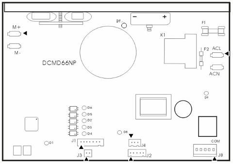
J1 console wire-7 PINs
| 1 | 2 | 3 | 4 | 5 | 6 | 7 |
| RPM | DRIVE EN | MOTOR EN | SLOW | FAST | GND | 12V |
J2 console wire-5 PINs
| 1 | 2 | 3 | 4 | 5 |
| VCC | ADC | GND | UP | DOWN |
J3 speed sensor
| 1 | 2 |
| GND | RPM |
J4 incline motor VR
| 1 | 2 | 3 |
| VCC | ADC | GND |
J6 AC AC Power input
| 1 | 2 |
| ACL | ACN |
J7 DC Power output
| 1 | 2 |
| M+ | M- |
J8 incline motor output
| 1 | 2 | 3 | 4 | 5 |
| COM | X | UP | X | DOWN |
LED pilot lamp
| D1 | Error | D | Console Power |
| D2 | Speed Increase/ Decrease | D9 | Incline UP/Down |
| D7 | DC Output Power |
1.3. Console PCB
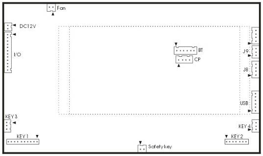
I/O Console wire
I/O Console wire
CP (ICP For program update
J3 Blue Tooth (BT)
J4 DC12V
J6 iHP PCB (USB)
J7 Hand Pulse
J9 Wireless HR receiver
J10 SAFE KEY
J14 PWM 12V power(fan)
KEY 1 Membrane
J17 Handle Button - Speed (KEY 3)
J18 Handle Button - Incline (KEY 4)
J19 Membrane (KEY 2)
2. Error Signal Check Steps And Solutions
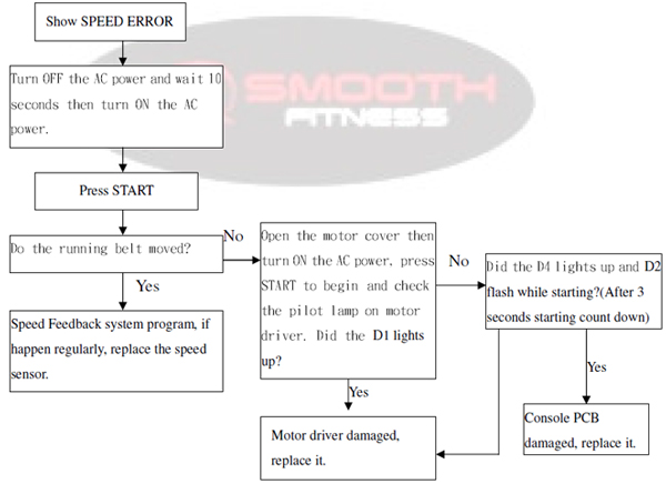
2.1.SPEED ERROR
Can not receive signal from speed sensor over 6 seconds while workout, all windows display will off, all output will stop, and show SPEED ERROR.
If this is a all new product that just finished assemble, there are more possibly in assemble problems, maybe connect wire not well or wire damaged while assemble.
Determine & Solution
2.2. E6
The incline AD parameter did not change over 7 seconds while operating the incline, incline function can not be use but other functions are normal to use.
If this is a all new product that just finished assemble, there are more possibly in assemble problems, maybe connect wire not well or wire damaged while assemble.
Determine & Solution
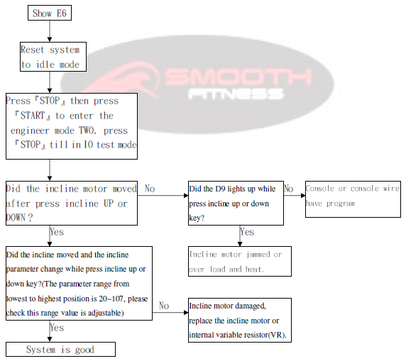
Before install a new incline motor or VR, have to sure the incline motor or VR in the incline level 0 condition.
2.3. E7
Incline motor AD parameter out of the range. under 15 / over 120 .
Determine & Solution

Before install a new incline motor or VR, have to sure the incline motor or VR in the incline level 0 condition.
3. Other Information
3.1. No Any Display On Console(No Power)

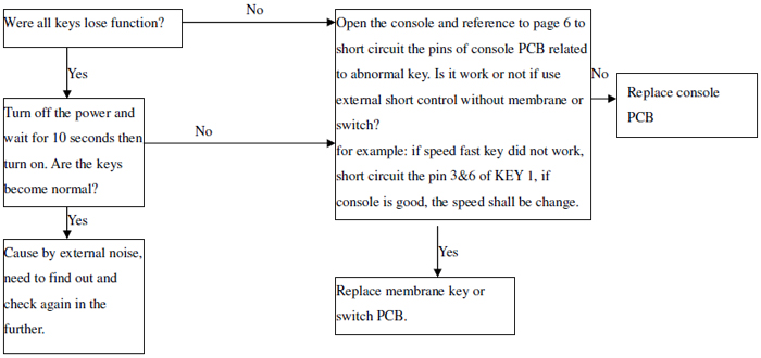
3.2. Key Lose Function
3.3. Real Speed Do Not To Fit In With Display Speed

4. Engineering Mode
4.1. Engineering Mode ONE Basic Settings
In idle mode, press and hold STOP then press Program Select to enter the mode.
4.1.1. Software information Message window show software version & modification date, press Enter to next setting.
4.1.2.Unit setting Message window show SET UNIT = KM , press FAST or SLOW can change to SET UNIT = EN , press Enter to next setting.
4.1.3.Perpetual calendar Select ON can edit the perpetual calendar.
4.1.4.Total used distance Message window show TOTAL DIST = , incline window show 000~999 km/mil, speed window will carry 1 if over 1000 km/mil, press Enter to next setting.
4.1.5.Total used time Message window show TOTAL TIME = , incline window show 000~999 hour, speed window will carry 1 if over 1000 hours, press Enter back to idle.
4.2. Engineering Mode TWO Test Mode
In idle mode, press and hold STOP then press Start to enter the mode.
4.2.1.Display test 1 Press STOP to next mode.
4.2.2.Display test 2 Press STOP to next mode.
4.2.3.Display test 3 Press STOP to next mode.
4.2.4.KEY test Dot-matrix window show KEY , each key has their own parameter show as below, press STOP to next mode.
| Key | Parameter | Key | Parameter |
|---|---|---|---|
| INCLINE UP | 100 | SPEED FAST | 120 |
| INCLINE DOWN | 101 | SPEED SLOW | 121 |
| START | 102 | BLUE TOOTH | 123 |
| ENTER | 103 | FAN | 124 |
| PROGRAM SELECT | 104 | SPEED 4 | 130 |
| INCLINE 2 | 110 | SPEED 6 | 131 |
| INCLINE 4 | 111 | SPEED 8 | 132 |
| INCLINE 6 | 112 | SPEED 10 | 133 |
| INCLINE 8 | 113 |
4.2.5.IO test mode Press START can trip the motor control relay, press FAST or SLOW can control the motor manual, press incline UP or DOWN can drive incline motor manually, time window show incline motor AD parameter 0~255, speed window show real-time speed that feedback from speed sensor, press STOP to display test 1 or press and hold STOP then press START back to idle.
4.3. Engineering Mode THREE Data default(Erase)
4.3.1.Erase the Custom settings In idle mode, press and hold STOP then press Enter , Custom settings will erase to default value.
4.3.2.Erase the total used time & distance In engineering mode ONE, press and hold STOP then press Enter , total used time & distance will erase and Custom settings will erase to default value.
4.4. Engineering Mode FOUR iHP Perpetual calendar edit
Press any one of the speed express key while in the IDLE mode, message window show iHP internal date and time, press Enter back to idle or press and hold any one of the speed express key to edit the perpetual calendar.
4.4.1.Set Year Message window show SET YEAR = XX (XX 2011= 11), press FAST or DOWN to set, press Enter to next setting.
4.4.2.Set Month Message window show SET MONTH = XX (XX 1~12) , press FAST or DOWN to set, press Enter to next setting.
4.4.3.Set Date Message window show SET DATE = XX (XX 1~31) , press FAST or DOWN to set, press Enter to next setting.
4.4.4.Set Hour Message window show SET HOUR = XX , press FAST or DOWN to set, press Enter to next setting.
4.4.5.Set Minute Message window show SET MINUTE = XX, press FAST or DOWN to set, press Enter back to idle.
5. Program Update
5.1. Install Software from PC Site
5.1.1.Un-zip the zipped file Programmer v5.41 to (1) PC-site AP (2) PC-site Driver, entry the (1) PC-site AP document then execute and install the Setup.

5.1.2.Entry the (2) PC-site Driver document, cursor on file 0E6A030D_8051ISPICP_v3.00 then click mouse right side and select Install ( I ).

5.2. Programmer Update
5.2.1.Connect the programmer to PC USB port, the LED2 & LED3 on programmer will be light up.

5.2.2.Execute the programmer update PC site software.
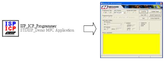
5.2.3.Settings:
5.2.3.1. Programmer Type ICP
5.2.3.2. MCU Part No MPC82G516
5.2.3.3. Programming Area Whole-chip
5.2.3.4. ISP-memory 0xFC00~0xFFFF(1KB)
5.2.3.5. Select HWBS / LOCK / OSCDN

5.2.4.Load burning code and update programmer click Load File Select and open the burning code click Update Programmer update ok
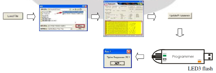
5.2.5.Programmer update success, pull out the programmer from PC.
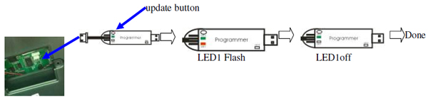
5.3. Program Update(switch ON the power input, console must be have power)
5.3.1.Open the small cover where on the back of console set->connect the programmer to console update port->press update button where on the programmer->programmer LED1 off after flash -> done