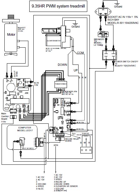
SERVICE MANUAL FOR:
9.35HR Specifications
Length: 71" (1807mm)
Width: 38" (970mm)
Running Area: 20" 52" (500mm 1320mm)
Weight of product: 220lbs (100kgs)
Shipping Weight: 247lbs (112kgs)
Speed Range: 0.5~11 mph (0.8~18 kph) in 0.1mph or 0.1kph increments
Incline Range: 0~15 levels
TFT TV Kit: No
Fold Up: No
Power Fold Up: No
Manual Adjustment Shock: Yes
Intelligent Suspension System: No
Swing Arm Suspension: Yes
Motion control: Yes
Hand Pulse Sensor: Yes
Wireless Pulse Sensor: 5KHz Receiver and with Polar T34 chest belt transmitter
Programs: Quick Start, Target time, Target distance, Target calories, Speed interval level 1~12, Incline interval level 1~12, Weight lost level 1~12, 5K Learning, Heart rate control
Power Requirement: 115vac 5% 16Amps and 230vac 5% 50/60Hz 9Amps
Motor: DC motor (Model:A1D 115vac model 90DCV and 230vac model 180VDC)
Emergency Stop: Pull the emergency stop key
9.45ST Specifications
Length: 72.8" (1848mm)
Width: 38.5" (977mm)
Running Area: 20" 60" (500mm 1524mm)
Weight of product: 216lbs (98kgs)
Shipping Weight: 250lbs (112kgs)
Speed Range: 0.5~11 mph (0.8~18 kph) in 0.1mph or 0.1kph increments
Incline Range: 0~15 levels
TFT TV Kit: No
Fold Up: Yes
Power Fold Up: No
Manual Adjustment Shock: No
Intelligent Suspension System: No
Swing Arm Suspension: Yes
Motion control: Yes
Hand Pulse Sensor: Yes
Wireless Pulse Sensor: 5KHz Receiver and with Polar T34 chest belt transmitter
Programs: Quick Start, Target time, Target distance, Target calories, Speed interval level 1~12, Incline interval level 1~12, Weight lost level 1~12, 5K Learning, Heart rate control
Power Requirement: 115vac �������± 5% 16Amps and 230vac �������± 5% 50/60Hz 9Amps
Motor: DC motor (Model:A1D 115vac model 90DCV and 230vac model 180VDC)
Emergency Stop: Pull the emergency stop key
9.45TV Specifications
Length: 72.8" (1848mm)
Width: 38.5" (977mm)
Running Area: 20" Ã?Â?Ã?Â?Ã?Â?Ã?Â? 60" (500mmÃ?Â?Ã?Â?Ã?Â?Ã?Â?1524mm)
Weight of product: 216lbs (98kgs)
Shipping Weight: 250lbs (112kgs)
Speed Range: 0.5~11 mph (0.8~18kph) in 0.1mph or 0.1kph increments
Incline Range: 0~15 levels
TFT TV Kit: Yes
Fold Up: No
Power Fold Up: No
Manual Adjustment Shock: Yes
Intelligent Suspension System: No
Swing Arm Suspension: Yes
Motion control: Yes
Hand Pulse Sensor: Yes
Wireless Pulse Sensor: 5KHz Receiver and with Polar T34 chest belt transmitter
Programs: Quick Start, Target time, Target distance, Target calories, Speed interval level 1~12, Incline interval level 1~12, Weight lost level 1~12, 5K Learning, Heart rate control
Power Requirement: 115vac �������± 5% 16Amps and 230vac �������± 5% 50/60Hz 9Amps
Motor: DC motor (Model:A1D 115vac model 90DCV and 230vac model 180VDC)
Emergency Stop: Pull the emergency stop key
9.35HR 9.45ST 9.45TV Console Operation
POWER ON:
Set the POWER SWITCH, located on the bottom of the left handle bar upright tube, to ON and insert the SAFETY KEY. All the LED lights will auto scan then display the factory default setting:
CALORIES window will display : 0
TIME window will display : 0.00
SPEED window will display : 0.0
INCLINE window will display : 0
HEART RATE window will display : P
SLEEP MODE:
The computer will automatically enter SLEEP MODE if left idle for 3 minutes without any input in POWER ON status. Press any button to return to POWER ON status when the computer is in SLEEP MODE.
3 SECONDS ALERT:
To ensure you are well prepared before the belt starts moving, every time you press the START button to start the belt, the SPEED window will countdown 3 seconds with the LED showing "3-2-1" then the belt will start moving.
PAUSE/STOP:
When the treadmill is running, press the STOP button to pause the treadmill. All figures on the display on the LED will freeze. Press START to resume the program and all displays will continue the performance until the program finishes. If you continue pressing the STOP twice, then all data will return to 0 and the treadmill will return to POWER ON status. If there is no action within 30 seconds, the treadmill will return to POWER ON status.
RECOVERY
Recovery is the feature to let the user test their physical condition after a workout. The recovery rating is determined by measuring how quickly the user's pulse slows down after the workout to justify the users physical condition. The faster the pulse slows down, the better the user's physical condition. User's can record their recovery rating after each workout to use for reference. To operate the RECOVERY feature, press the "REC" button after completing a workout. The treadmill will enter the PAUSE/STOP status. Put both hands on the hand pulse sensors within 10 seconds (for models equipped with a chest belt pulse transmitter, keep the chest belt on, no need to hold the hand pulse). The pulse receiver will scan and detect the user's pulse in 10 seconds and enter the RECOVERY procedure. TIME counts down from 01:00 to 00:00. The SPEED LED window will show the RECOVER RATING after the one-minute count down. Record the rating for future comparison.
During the RECOVERY procedure, if you want to stop the RECOVERY and stop workout, press the STOP/ENTER button and return to POWER ON status.
During the RECOVERY procedure, if you want to continue the previous program, press the START button to continue the previous program.
After pressing the RECOVERY button, if the pulse receiver fails to scan and receive the user's pulse the computer will stay at PAUSE/STOP status. Press the STOP/ENTER button to return to POWER ON status or press the START button to continue the previous program.
When training in the COOL DOWN mode, the RECOVERY mode cannot be used.
ENGLISH/METRIC CONVERSION:
The treadmill computer display can show ENGLISH and METRIC information. The factory should have the proper setting on this for different markets. In case that the treadmill needs to be converted between METRIC and ENGLISH readout, please follow the procedure as below:
Set the POWER SWITCH to ON. Press the ENTER button on the computer and hold it. Insert the SAFETY KEY then release the ENTER button. The computer will sound one short beep and METRIC LED light up.
Press the ENTER button to switch between METRIC/ENGLISH and press the STOP button to confirm the selection and return to the POWER ON status.
QUICK START:
When the treadmill is in POWER ON status, press the START button to activate the QUICK START program. The speed will start from 0.5MPH/0.8KMPH. Press the SPEED UP/DOWN button to change the speed. Press the INCLINE switch to elevate the treadmill. The TIME, CALORIES and DISTANCE will count up from 0.
PROGRAM:
To select other programs, you will need to select the USER first. Press the SPEED UP/DOWN button to select the USER CODE from U1 to U9 then press the ENTER button to confirm the user code. If the user information has been previously input, press the ENTER button again and hold it for 5 seconds then the computer will skip the user information set up procedure and enter the program select procedure. To input the new user information, please follow the procedure as below:
WEIGHT set up ���¢�������� After the User Code confirmation procedure, The CALORIES/CAL PER HOUR display will show the default or previous setting and begin blinking. Press the SPEED UP/DOWN button to adjust the user weight information then press ENTER to confirm.
HEIGHT set up ���¢�������� After the WEIGHT set up procedure, the TIME/DISTANCE display will show the default or previous setting and begin blinking. Press the SPEED UP/DOWN button to adjust the user height information then press ENTER to confirm.
AGE set up ���¢�������� After the HEIGHT set up procedure, the INCLINE/LEVEL display will show the default or previous setting and begin blinking. Press the SPEED UP/DOWN button to adjust the user age information then press ENTER to confirm.
GOAL COURSE TIME:
When the computer is in POWER ON status, press the button  on the console. The LED on button will light up. If no buttons are pressed after this within 3 minutes the program will return to POWER ON status. If you wish to return to POWER ON status, press the STOP button any time.
The TIME LED will light up, show the preset time as 30:00 and blink. After, press the button. Press the SPEED UP/DOWN buttons to set your ideal workout time then press the ENTER button to confirm. Then press the START button to start. After pressing the START button the TIME counts down from the preset time. The other information counts up until the treadmill stops. The Speed starts from 2MPH/3.2KMPH and the incline starts from level 0. Press the SPEED UP/DOWN buttons to adjust the speed. Press the INCLINE UP/DOWN buttons to adjust the incline level.
During exercise press STOP to pause the program. Speed and Incline Level return to the beginning levels while the other information (Time, Distance, Calories) is paused. To recall values and resume exercising press START. Pressing the STOP button again within 30 seconds returns all data to zero and the computer returns to POWER ON status. If no buttons are pressed within 30 seconds the computer automatically returns to POWER ON status and all data returns to zero.
GOAL COURSE DISTANCE:
When the computer is in POWER ON status press the  button on the console. The LED on button lights up. If no buttons are pressed within 3 minutes the program will return to POWER ON status. If you wish to return to POWER ON status, press the STOP button any time.
The DISTANCE LED will light up, show the preset distance as 0 and begin blinking. After press the button. Press the SPEED UP/DOWN buttons to set up the ideal distance then press the ENTER button to confirm. Then press the START button to start. After pressing the START button the DISTANCE counts down from the preset distance. The other information counts up until the treadmill stops. The Speed starts from 2MPH/3.2KMPH and incline starts from level 0.
During exercise, press STOP to pause the program. Speed and Incline Level return to the beginning levels while the other information (Time, Distance, Calories) is paused. To recall values and resume exercising press START. Pressing the STOP button again within 30 seconds returns all data to zero and the computer returns to POWER ON status. If no buttons are pressed within 30 seconds the computer automatically returns to POWER ON status and all data returns to zero.
GOAL COURSE CALORIES:
When the computer is in POWER ON status press the  button on the console. The LED button lights up. If no buttons are pressed within 3 minutes the program will return to POWER ON status.
If you wish to return to POWER ON status, press the STOP button any time.
The CALORIES LED will light up and show the preset calories burned as 0 and blinking. Next, press the button. Press the SPEED UP/DOWN buttons to set up the desired calories then press the ENTER button to confirm. Then press the START button to start. After pressing the START button, the CALORIES count down from the preset calories. The other information counts up until the treadmill stops. The Speed starts from 2MPH/3.2KMPH and the incline starts from level 0. Press the SPEED UP/DOWN buttons to adjust the speed. Press the INCLINE UP/DOWN buttons to adjust the incline level.
During exercise press STOP to pause the program. The Speed and Incline Level return to the beginning levels while the other information (Time, Distance, Calories) is paused. To recall values and resume exercising press START. Pressing the STOP button again within 30 seconds returns all data to zero and the computer returns to POWER ON status. If no buttons are pressed within 30 seconds the computer automatically returns to POWER ON status and all data returns to zero.
KILLER HILLS:
When the treadmill is in PROGRAM SELECT status, press the  button. The LEVEL display will show 01 and be blinking. There are total of 12 different workout levels that can be selected. Press the SPEED UP/DOWN button to select the level then press the ENTER button. The TIME LED will show a pre-set workout time of 24 minutes. Press the SPEED UP/DOWN button to adjust the time, 4 minutes per segment for every adjustment. Press the ENTER button to confirm the workout time then press the START button to start the program. The program will start with 2 minutes in MIN. GRADE% and 2 minutes in MAX. GRADE%. Repeat in 4 minute segments until the time counts down to zero.
Pre-set speed 2.0MPH/3.2KMPH, adjust the speed using the SPEED UP/DOWN BUTTON,
KILLER HILLS WORKOUT
| LEVEL |
MIN. GRADE% |
MAX. GRADE% |
| 1 |
0 |
4 |
| 2 |
1 |
5 |
| 3 |
2 |
6 |
| 4 |
3 |
7 |
| 5 |
4 |
8 |
| 6 |
5 |
9 |
| 7 |
6 |
10 |
| 8 |
7 |
11 |
| 9 |
8 |
12 |
| 10 |
9 |
13 |
| 11 |
10 |
14 |
| 12 |
11 |
15 |
SPEED INTERVAL:
When the treadmill is in PROGRAM SELECT status, press  button. The LEVEL display will show a blinking 01. There are a total of 12 different workout levels that can be selected. Press the SPEED UP/DOWN button to select the level then press the ENTER button. The TIME LED will show a pre-set workout time of 24 minutes. Press the SPEED UP/DOWN button to adjust the time, 4 minutes per segment for every adjustment. Press the ENTER button to confirm the workout time then press the START button to start the program. The program will start with 2 minutes in MIN SPEED and 2 minutes in MAX SPEED. Repeat this in 4 minute segments until the time counts down to zero.
Pre-set INCLINE LEVEL at 0%. Adjust the incline level using the INCLINE UP/DOWN button during the workout.
SPEED INTERVAL WORKOUT
| LEVEL |
MIN. SPEED |
MAX. SPEED |
| 1 |
1.8 |
3.0 |
| 2 |
2.0 |
3.4 |
| 3 |
2.2 |
3.8 |
| 4 |
2.4 |
4.2 |
| 5 |
2.6 |
4.6 |
| 6 |
2.8 |
5.0 |
| 7 |
3.0 |
5.4 |
| 8 |
3.2 |
5.8 |
| 9 |
3.4 |
6.2 |
| 10 |
3.6 |
6.6 |
| 11 |
3.8 |
7.0 |
| 12 |
4.0 |
7.2 |
WEIGHT LOSS:
When the treadmill is in PROGRAM SELECT status, press the  button. The LEVEL will display a blinking 01. There are a total of 12 different workout levels that can be selected. Press the SPEED UP/DOWN button to select the level then press the ENTER button. The TIME LED will show a pre-set workout time of 30 minutes. Press the SPEED UP/DOWN button to adjust the time, 5 minutes per segment for every adjustment. Press the ENTER button to confirm the workout time then press the START button to start the program. The program will start with 2 .5 minutes in MIN SPEED/GRADE% and 2.5 minutes in MAX SPEED/GRADE%. Repeat in 5 minute segments until the time counts down to zero.
WEIGHT LOSS WORKOUT
| LEVEL |
MIN. SPEED |
MAX. SPEED |
MINI. GRADE% |
MAX GRADE% |
| 1 |
1.6 |
2.8 |
0 |
3 |
| 2 |
1.8 |
3.0 |
0 |
4 |
WEIGHT LOSS WORKOUT
LEVEL
MIN. SPEED
MAX. SPEED
MINI. GRADE%
MAX GRADE%
5K SELF LEARNING/COMPETITION:
When the treadmill is in PROGRAM SELECT status, press the  button. The DISTANCE LED will show 5(KM)/3(MILE). For new users, there is a pre-set speed and incline% program in the computer. Press the START button to start the program. The user can change the speed and incline level during the workout. The DISTANCE will count down to zero then stop. The result time and calories will be saved and shown on the display so the user can select this program again and to challenge himself using the same program.
HEART RATE CONTROL:
When the treadmill is in PROGRAM SELECT status, press the  button.
TIME SET UP ���¢�������� After selecting the HEART RATE CONTROL program, the TIME LED will show a blinking pre-set workout time of 60:00. Press the SPEED UP/DOWN button to adjust the workout time then press the ENTER button to confirm. Press the START button to start the program. During the program please make sure to wear the chest belt or hold the hand pulse contact sensor on the handle bar at all times. Exercising without the chest belt or failure to hold the contact sensor will cause the program fail and discontinue.
WARM UP ���¢�������� After completing the TIME set up and starting the program, there is a 3 minute WARM UP program to help you reach the minimum target workout heart rate. The speed will start from 2MILE/3.2KM and the incline level will start from 0. If the actual pulse rate does not reach the minimum target workout heart rate, the speed will increase 0.5MILE/0.8KM every 15 seconds. When the actual pulse rate reaches the minimum target workout heart rate, the speed will stop increasing and continue the same speed until the 3 minute warm up is complete and then go into the HEART RATE CONTROL main program. If you cannot reach the minimum target workout heart rate in 3 minutes, the program will continue the 2nd 3 minute WARM UP program. During the 2nd WARM UP program, the speed will remain the same speed as in the first WARM UP program. If the actual pulse rate cannot reach the minimum target workout heart rate, the incline level will add 1% every 15 seconds. When the actual pulse rate reaches the minimum target workout heart rate, the incline will stop changing and continue the same speed and same incline level until the time counts down to zero, then enters the HEART RATE CONTROL main program. If during the 2nd WARM UP the user still can not reach the minimum target workout heart rate, the computer will continue on to the 3rd WARM UP procedure for 3 minutes and both speed and incline level will remain the same as the 2nd WARM UP until the time counts down to zero. If the 3rd WARM UP program still cannot bring up the actual pulse rate to the minimum target workout heart rate, the program will stop and SPEED LED will show FAIL.
HEART RATE CONTROL MAIN PROGRAM ���¢�������� After the actual pulse rate reaches the minimum target workout heart rate and completes the warm up program, the computer will go into the main program and the time will count down from the pre-set time. During the main program, if the actual pulse rate cannot reach the maximum target workout heart rate, the incline level will be increased by 1% every 15 seconds until the pulse rate reaches the maximum target workout heart rate or the incline level will increase by 15%. After the incline level increases to 15% but still does not reach the maximum target workout heart rate the speed will be increase by 0.5MILE/0.8KM every 15 seconds until the pulse rate reaches the maximum target workout heart rate. If the actual pulse is higher than the maximum target workout heart rate, then the incline will be reduced 1% every 15 seconds until the actual heart rate meets the maximum target workout heart rate or the incline level will lower to 0%. Then the speed will be reduced by 0.5MILE/0.8KM every 15 seconds until the actual pulse meets the maximum target workout heart rate.
COOL DOWN ���¢�������� After completing the HEART RATE CONTROL program and the time counts down to zero, you will start the one-minute cool down program. The incline will return to 0% and the speed will lower to 2 MPH/3.2 Km/h as the time counts down from 1:00.
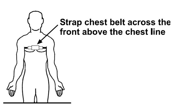
USING THE CHEST BELT HEART RATE MONITOR: For proper operation, the chest belt should be worn with the monitor strapped across the front of your body just above the chest line as shown in the drawing on the right. The monitor needs a little body heat and moisture in order to work properly. To ensure correct operation you may want to wet the two rubber pickups under the belt prior to exercising.
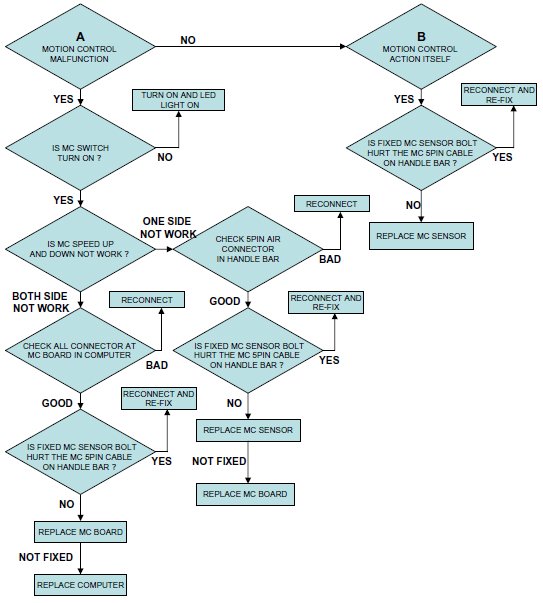
MOTION CONTROL:
Walking belt speed can be increased, decreased or stopped using the Motion Control sensors on the handlebars. To do this follow the instructions below:
NOTE: Photos may differ slightly from your treadmill.
1. Press the MOTION CONTROL button on the console to switch the motion control function on and off:
When the LED light is ON, the MOTION CONTROL is active.
When the LED light is OFF, the MOTION CONTROL is off.
2.After switching on the MOTION CONTROL, wave your right hand approximately 6 inches above the motion sensor on the right handle bar to increase the speed. The sensor will sound one short BEEP per scan and speed up by 0.1 MPH per BEEP. Holding your right hand approximately 6 inches above the right sensor constantly results in the sensor sounding one long BEEP per second and speeding up by 0.5 MPH per second.
3.Wave you left hand approximately 6 inches above the motion sensor on the left handle bar to decrease the speed. The sensor will sound one short BEEP per scan and decrease speed by 0.1 MPH. Holding your left hand approximately 6 inches above the left sensor constantly results in the sensor sounding one long BEEP per second and decreasing speed by 0.5 MPH per second
4.Wave both hands approximately 6 inches above both motion sensors at the same time. The sensor will sound two short BEEP sounds then stop the belt.
Always switch off the motion control function by pressing the MOTION CONTROL button on the console before turning off the power to the treadmill.
9.35HR Parts List
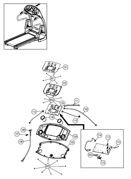
9.35HR-100 Complete Computer Console
| Item No. |
Description |
Qty. |
Part No. |
| 101 |
Overlay |
1 |
9.35HR-101 |
| 102 |
Computer Insert |
1 |
9.35HR-102 |
| 103 |
Console PC Board |
1 |
9.35HR-103 |
| 104 |
Console Housing ���¢�������� Upper |
1 |
9.35HR-104 |
| 105 |
Console Housing ���¢�������� Bottom |
1 |
9.35HR-105 |
| 106 |
Safety Key Base |
1 |
9.35HR-106 |
| 107 |
Safety Key |
1 |
9.35HR-107 |
| 108 |
Safety Key Wire ���¢�������� Upper |
1 |
9.35HR-108 |
| 109 |
Computer Wire ���¢�������� Upper |
1 |
9.35HR-109 |
| 110 |
Computer Ground Wire |
1 |
9.35HR-110 |
| 111 |
Hand Pulse Wire ���¢�������� Upper |
2 |
9.35HR-111 |
| 112 |
E ���¢�������� Prom |
1 |
9.35HR-112 |
| 113 |
Motion Control Board |
1 |
9.35HR-113 |
| 114 |
Motion Control Board Wire |
1 |
9.35HR-114 |
| 115 |
Motion Control Sensor Wire |
2 |
9.35HR-115 |
| 116 |
Water Bottle Holder |
2 |
9.35HR-116 |
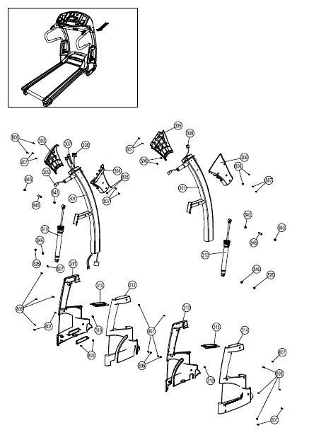
9.35HR-200 Complete Handle Bar Components
| Item No. |
Description |
Qty. |
Part No. |
| 201 |
Handle Bar Upright |
2 |
9.35HR-201 |
| 202 |
Handle Bar Upright Foam Grip |
2 |
9.35HR-202 |
| 203 |
Front Handle Bar |
1 |
9.35HR-203 |
| 204 |
Front Handle Bar Foam Grip-Short |
1 |
9.35HR-204 |
| 205 |
Front Handle Bar Foam Grip-Long |
2 |
9.35HR-205 |
| 206 |
Hand Pulse Set |
2 |
9.35HR-206 |
| 207 |
Motion Control |
2 |
9.35HR-207 |
| 208 |
Motion Control Base |
2 |
9.35HR-208 |
9.35HR-300 Complete Upright Components
| Item No. |
Description |
Qty. |
Part No. |
| 301 |
Upright |
2 |
9.35HR-301 |
| 303 |
Upright Cover-LL |
1 |
9.35HR-303 |
| 304 |
Upright Cover-LR |
1 |
9.35HR-304 |
| 305 |
Upright Cover-RL |
1 |
9.35HR-305 |
| 306 |
Upright Cover-RR |
1 |
9.35HR-306 |
| 307 |
Safety Key Wire ���¢�������� Middle |
1 |
9.35HR-307 |
| 308 |
Computer Wire ���¢�������� Upper |
1 |
9.35HR-308 |
| 309 |
Motion Control Sensor Wire - Middle |
2 |
9.35HR-309 |
| 310 |
Adjustable Cylinder |
2 |
9.35HR-310 |
| 311 |
Upright Plastic Shroud ���¢�������� LL |
1 |
9.35HR-311 |
| 312 |
Upright Plastic Shroud ���¢�������� LR |
1 |
9.35HR-312 |
| 313 |
Upright Plastic Shroud ���¢�������� RL |
1 |
9.35HR-313 |
| 314 |
Upright Plastic Shroud ���¢�������� RR |
1 |
9.35HR-314 |
| 315 |
Adjustable Cylinder Cover - Upper |
2 |
9.35HR-315 |
| 318 |
Fixing Inserts |
2 |
9.35HR-316 |
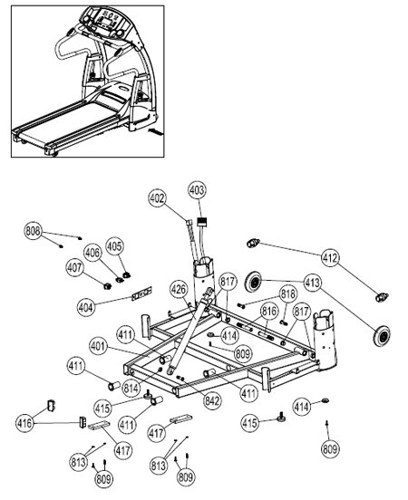
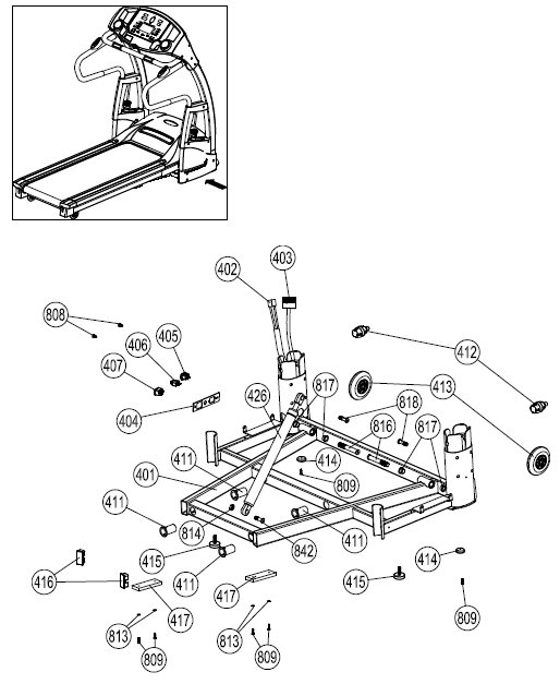
9.35HR-400 Complete Base Frame Components
| Item No. |
Description |
Qty. |
Part No. |
| 401 |
Base Frame |
1 |
9.35HR-401 |
| 402 |
Safety Key Wire ���¢�������� Lower |
1 |
9.35HR-402 |
| 403 |
Computer Wire ���¢��������Lower |
1 |
9.35HR-403 |
| 404 |
Power Switch Plate Cover |
1 |
9.35HR-404 |
| 405 |
Power Switch Plate |
1 |
9.35HR-405 |
| 406 |
Power Breaker |
1 |
9.35HR-406 |
| 407 |
Power Switch |
1 |
9.35HR-407 |
| 411 |
Bushing |
4 |
9.35HR-411 |
| 412 |
Fix Bolt Sets |
2 |
9.35HR-412 |
| 413 |
Front Caster |
2 |
9.35HR-413 |
| 414 |
Rubber Cushion |
2 |
9.35HR-414 |
| 415 |
Level Adjuster |
2 |
9.35HR-415 |
| 416 |
Base Frame End Cap |
2 |
9.35HR-416 |
| 417 |
Cushion |
2 |
9.35HR-417 |
| 426 |
Shock |
1 |
9.35HR-426 |
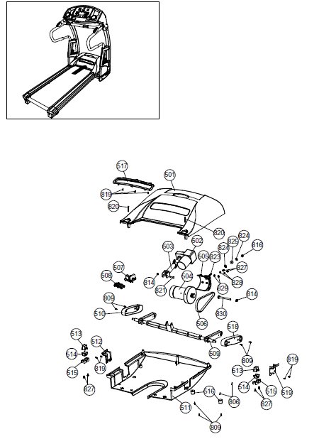
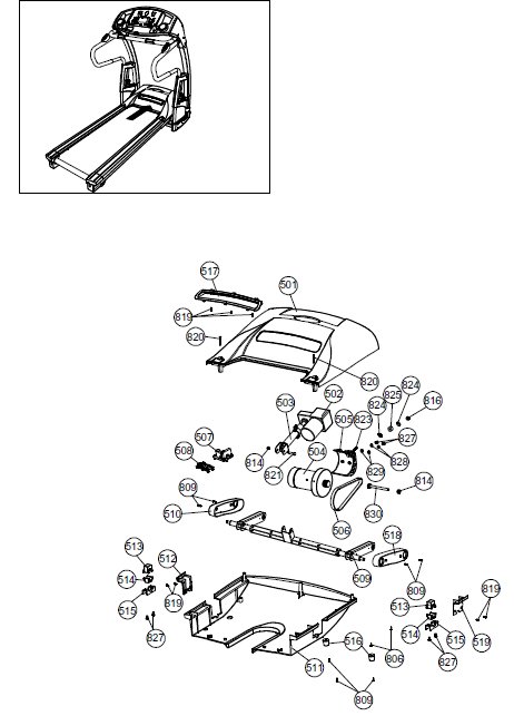
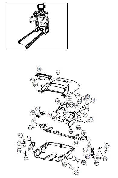
9.35HR-500 Complete Motor Components
| Item No. |
Description |
Qty. |
Part No. |
| 501 |
Motor Hood |
1 |
9.35HR-501 |
| 502 |
Elevation Motor |
1 |
9.35HR-502 |
| 503 |
Elevation Gear Sleeve |
1 |
9.35HR-503 |
| 504 |
Driving Motor |
1 |
9.35HR-504 |
| 505 |
Motor Holder |
1 |
9.35HR-505 |
| 506 |
Driving Belt |
1 |
9.35HR-506 |
| 507 |
Motor Control Board |
1 |
9.35HR-507 |
| 508 |
Elevation Control Board |
1 |
9.35HR-508 |
| 509 |
Elevation Support Tube |
1 |
9.35HR-509 |
| 510 |
Elevation Support Tube Cover - LEFT |
1 |
9.35HR-510 |
| 511 |
Motor Bottom Cover |
1 |
9.35HR-511 |
| 512 |
Deck Frame Side Cover - LEFT |
1 |
9.35HR-512 |
| 513 |
Plastic Clamp - TOP |
2 |
9.35HR-513 |
| 514 |
Plastic Clamp - BOTTOM |
2 |
9.35HR-514 |
| 515 |
Elevation Support |
2 |
9.35HR-515 |
| 516 |
Deck Rubber Cushion |
2 |
9.35HR-516 |
| 517 |
Rear Vent Cover |
1 |
9.35HR-517 |
| 518 |
Elevation Support Tube Cover - RIGHT |
1 |
9.35HR-518 |
| 519 |
Deck Frame Side Cover ���¢�������� RIGHT |
1 |
9.35HR-519 |
9.35HR-600 Complete Running Deck Components
| Item No. |
Description |
Qty. |
Part No. |
| 601 |
Running Belt |
1 |
9.35HR-601 |
| 602 |
Side Rail |
2 |
9.35HR-602 |
| 603 |
Running Deck |
1 |
9.35HR-603 |
| 604 |
Side Rail End Cap - LEFT |
1 |
9.35HR-604 |
| 605 |
Side Rail End Cap - RIGHT |
1 |
9.35HR-605 |
9.35HR-700 Complete Deck Frame Components
| Item No. |
Description |
Qty. |
Part No. |
| 701 |
Deck Frame |
1 |
9.35HR-701 |
| 702 |
Front Roller Shaft |
1 |
9.35HR-702 |
| 703 |
Front Roller Tube |
1 |
9.35HR-703 |
| 704 |
Roller Bearing 6202 |
4 |
9.35HR-704 |
| 705 |
Rear Roller Shaft |
1 |
9.35HR-705 |
| 706 |
Rear Roller Tube |
1 |
9.35HR-706 |
| 707 |
Running Deck Support Tube |
1 |
9.35HR-707 |
| 708 |
Deck Frame ���¢�������� Rear |
1 |
9.35HR-708 |
| 709 |
Steady Frame |
1 |
9.35HR-709 |
| 413 |
Rear Caster |
2 |
9.35HR-413 |
9.35HR-800 Complete Hardware Pack
| Item No. |
Description |
Qty. |
Part No. |
| 801 |
?6 Ã?Â?Ã?Â?Ã?Â?Ã?Â? 12mm Screws |
10 |
9.35HR-801 |
| 802 |
M4 Ã?Â?Ã?Â?Ã?Â?Ã?Â? 6mm Screws |
12 |
9.35HR-802 |
| 803 |
M8 Ã?Â?Ã?Â?Ã?Â?Ã?Â? 12mm Screws |
8 |
9.35HR-803 |
| 804 |
M8 Ã?Â?Ã?Â?Ã?Â?Ã?Â? 15mm Bolt |
3 |
9.35HR-804 |
| 805 |
M8 Ã?Â?Ã?Â?Ã?Â?Ã?Â? 50mm Bolt |
12 |
9.35HR-805 |
| 806 |
# 8 Ã?Â?Ã?Â?Ã?Â?Ã?Â? 20mm Screw |
20 |
9.35HR-806 |
| 807 |
4 Ã?Â?Ã?Â?Ã?Â?Ã?Â? 15mm Thread Cutting Screw |
19 |
9.35HR-807 |
| 808 |
M5 Ã?Â?Ã?Â?Ã?Â?Ã?Â? 10mm Screws |
2 |
9.35HR-808 |
| 809 |
M8 Ã?Â?Ã?Â?Ã?Â?Ã?Â? 16 Screws |
20 |
9.35HR-809 |
| 813 |
Washer |
4 |
9.35HR-813 |
| 814 |
Nylon Nut |
6 |
9.35HR-814 |
| 816 |
M14 Ã?Â?Ã?Â?Ã?Â?Ã?Â? 90 Screws |
3 |
9.35HR-816 |
| 817 |
Bearing |
4 |
9.35HR-817 |
| 818 |
M10 Ã?Â?Ã?Â?Ã?Â?Ã?Â? 35mm Screws |
10 |
9.35HR-818 |
| 819 |
M8 Ã?Â?Ã?Â?Ã?Â?Ã?Â? 10mm Screws |
7 |
9.35HR-819 |
| 820 |
M8 Ã?Â?Ã?Â?Ã?Â?Ã?Â? 50mm Screws |
2 |
9.35HR-820 |
| 821 |
M10 Ã?Â?Ã?Â?Ã?Â?Ã?Â? 63mm Bolts |
1 |
9.35HR-821 |
| 822 |
Fixed Block |
8 |
9.35HR-822 |
| 823 |
M8 Ã?Â?Ã?Â?Ã?Â?Ã?Â? 120mm Bolts |
8 |
9.35HR-823 |
| 824 |
Plate Washer |
2 |
9.35HR-824 |
| 825 |
Spring |
1 |
9.35HR-825 |
| 826 |
M8 Nylon Nut |
2 |
9.35HR-826 |
| 827 |
M8 Ã?Â?Ã?Â?Ã?Â?Ã?Â? 20mm Screws |
6 |
9.35HR-827 |
| 828 |
Spring Washer |
10 |
9.35HR-828 |
| 829 |
Washer |
2 |
9.35HR-829 |
| 830 |
M10 Ã?Â?Ã?Â?Ã?Â?Ã?Â? 136mm Screws |
1 |
9.35HR-830 |
| 832 |
M8 Ã?Â?Ã?Â?Ã?Â?Ã?Â? 25mm Screws |
8 |
9.35HR-832 |
| 833 |
Hexagon Nut |
8 |
9.35HR-833 |
| 834 |
M6 Ã?Â?Ã?Â?Ã?Â?Ã?Â? 70mm Bolts |
3 |
9.35HR-834 |
| 838 |
M10 Ã?Â?Ã?Â?Ã?Â?Ã?Â? 43mm Bolts |
2 |
9.35HR-838 |
| 839 |
Cushion Pad |
8 |
9.35HR-839 |
| 840 |
M10 Ã?Â?Ã?Â?Ã?Â?Ã?Â? 40mm Screws |
1 |
9.35HR-840 |
| 841 |
M6 Ã?Â?Ã?Â?Ã?Â?Ã?Â? 10mm Screws |
2 |
9.35HR-841 |
| 842 |
M10 Ã?Â?Ã?Â?Ã?Â?Ã?Â? 30mm Allen Head Bolt |
2 |
9.35HR-842 |
| 843 |
M8 Ã?Â?Ã?Â?Ã?Â?Ã?Â? 15mm Allen Head Bolt |
4 |
9.35HR-843 |
| 845 |
13 Ã?Â?Ã?Â?Ã?Â?Ã?Â? 42mm Shaft |
2 |
9.35HR-845 |
| 846 |
#8 Ã?Â?Ã?Â?Ã?Â?Ã?Â? 23mm Washer |
2 |
9.35HR-846 |
9.35HR-100 Complete Computer Console
Item No.
Description
Qty.
Part No.
102
Computer Insert
1
9.35HR-102
103
Console PC Board
1
9.35HR-103
104
Console Housing ���¢�������� Upper
1
9.35HR-104
105
Console Housing ���¢�������� Bottom
1
9.35HR-105
106
Safety Key Base
1
9.35HR-106
107
Safety Key
1
9.35HR-107
108
Safety Key Wire ���¢�������� Upper
1
9.35HR-108
109
Computer Wire ���¢�������� Upper
1
9.35HR-109
110
Computer Ground Wire
1
9.35HR-110
111
Hand Pulse Wire ���¢�������� Upper
2
9.35HR-111
112
E ���¢�������� Prom
1
9.35HR-112
113
Motion Control Board
1
9.35HR-113
114
Motion Control Board Wire
1
9.35HR-114
115
Motion Control Sensor Wire
2
9.35HR-115
116
Water Bottle Holder
2
9.35HR-116
9.35HR-200 Complete Handle Bar Components
Item
Description
Qty.
Part No.
201
Handle Bar Upright
2
9.35HR-201
202
Handle Bar Upright Foam Grip
2
9.35HR-202
203
Front Handle Bar
1
9.35HR-203
204
Front Handle Bar Foam Grip-Short
1
9.35HR-204
205
Front Handle Bar Foam Grip-Long
2
9.35HR-205
206
Hand Pulse Set
2
9.35HR-206
207
Motion Control
2
9.35HR-207
208
Motion Control Base
2
9.35HR-208
9.35HR-300 Complete Upright Components
Item
Description
Qty.
Part No.
303
Upright Cover-LL
1
9.35HR-303
304
Upright Cover-LR
1
9.35HR-304
305
Upright Cover-RL
1
9.35HR-305
306
Upright Cover-RR
1
9.35HR-306
307
Safety Key Wire ���¢�������� Middle
1
9.35HR-307
308
Computer Wire ���¢�������� Upper
1
9.35HR-308
309
Motion Control Sensor Wire - Middle
2
9.35HR-309
310
Adjustable Cylinder
2
9.35HR-310
311
Upright Plastic Shroud ���¢�������� LL
1
9.35HR-311
312
Upright Plastic Shroud ���¢�������� LR
1
9.35HR-312
313
Upright Plastic Shroud ���¢�������� RL
1
9.35HR-313
314
Upright Plastic Shroud ���¢�������� RR
1
9.35HR-314
315
Adjustable Cylinder Cover - Upper
2
9.35HR-315
318
Fixing Inserts
2
9.35HR-316
9.35HR-400 Complete Base Frame Components
Item
Description
Qty.
Part No.
401
Base Frame
1
9.35HR-401
402
Safety Key Wire ���¢�������� Lower
1
9.35HR-402
403
Computer Wire ���¢��������Lower
1
9.35HR-403
404
Power Switch Plate Cover
1
9.35HR-404
405
Power Switch Plate
1
9.35HR-405
406
Power Breaker
1
9.35HR-406
407
Power Switch
1
9.35HR-407
412
Fix Bolt Sets
2
9.35HR-412
413
Front Caster
2
9.35HR-413
414
Rubber Cushion
2
9.35HR-414
415
Level Adjuster
2
9.35HR-415
416
Base Frame End Cap
2
9.35HR-416
9.35HR-500 Complete Motor Components
Item
Description
Qty.
Part No.
501
Motor Hood
1
9.35HR-501
502
Elevation Motor
1
9.35HR-502
503
Elevation Gear Sleeve
1
9.35HR-503
504
Driving Motor
1
9.35HR-504
505
Motor Holder
1
9.35HR-505
506
Driving Belt
1
9.35HR-506
507
Motor Control Board
1
9.35HR-507
508
Elevation Control Board
1
9.35HR-508
509
Elevation Support Tube
1
9.35HR-509
510
Elevation Support Tube Cover - LEFT
1
9.35HR-510
511
Motor Bottom Cover
1
9.35HR-511
512
Deck Frame Side Cover - LEFT
1
9.35HR-512
513
Plastic Clamp - TOP
1
9.35HR-513
514
Plastic Clamp - BOTTOM
1
9.35HR-514
515
Elevation Support
1
9.35HR-515
516
Deck Rubber Cushion
1
9.35HR-516
517
Rear Vent Cover
1
9.35HR-517
518
Elevation Support Tube Cover - RIGHT
1
9.35HR-518
519
Deck Frame Side Cover ���¢�������� RIGHT
1
9.35HR-519
9.35HR-600 Complete Running Deck Components
Item
Description
Qty.
Part No.
601
Running Belt
1
9.35HR-601
602
Side Rail
2
9.35HR-602
603
Running Deck
1
9.35HR-603
604
Side Rail End Cap - LEFT
1
9.35HR-604
605
Side Rail End Cap - RIGHT
1
9.35HR-605
9.35HR-700 Complete Deck Frame Components
Item
Description
Qty.
Part No.
701
Deck Frame
1
9.35HR-701
702
Front Roller Shaft
1
9.35HR-702
703
Front Roller Tube
1
9.35HR-703
704
Roller Bearing 6202
4
9.35HR-704
705
Rear Roller Shaft
4
9.35HR-705
706
Rear Roller Tube
1
9.35HR-706
707
Running Deck Support Tube
1
9.35HR-707
708
Deck Frame ���¢�������� Rear
1
9.35HR-708
709
Steady Frame
1
9.35HR-709
413
Rear Caster
2
9.35HR-413
9.35HR-800 Complete Hardware Pack
Item
Description
Qty.
Part No.
801
?6 Ã?Â?Ã?Â?Ã?Â?Ã?Â? 12mm Screws
10
9.35HR-801
802
M4 Ã?Â?Ã?Â?Ã?Â?Ã?Â? 6mm Screws
12
9.35HR-802
803
M8 Ã?Â?Ã?Â?Ã?Â?Ã?Â? 12mm Screws
8
9.35HR-803
804
M8 Ã?Â?Ã?Â?Ã?Â?Ã?Â? 15mm Bolt
3
9.35HR-804
805
M8 Ã?Â?Ã?Â?Ã?Â?Ã?Â? 50mm Bolt
12
9.35HR-805
806
# 8 Ã?Â?Ã?Â?Ã?Â?Ã?Â? 20mm Screw
20
9.35HR-806
807
4 Ã?Â?Ã?Â?Ã?Â?Ã?Â? 15mm Thread Cutting Screw
19
9.35HR-807
808
M5 Ã?Â?Ã?Â?Ã?Â?Ã?Â? 10mm Screws
2
9.35HR-808
809
M8 Ã?Â?Ã?Â?Ã?Â?Ã?Â? 16 Screws
20
9.35HR-809
814
Nylon Nut
6
9.35HR-814
816
M14 Ã?Â?Ã?Â?Ã?Â?Ã?Â? 90 Screws
3
9.35HR-816
818
M10 Ã?Â?Ã?Â?Ã?Â?Ã?Â? 35mm Screws
10
9.35HR-818
819
M8 Ã?Â?Ã?Â?Ã?Â?Ã?Â? 10mm Screws
7
9.35HR-819
820
M8 Ã?Â?Ã?Â?Ã?Â?Ã?Â? 50mm Screws
2
9.35HR-820
821
M10 Ã?Â?Ã?Â?Ã?Â?Ã?Â? 63mm Bolts
1
9.35HR-821
822
Fixed Block
8
9.35HR-822
823
M8 Ã?Â?Ã?Â?Ã?Â?Ã?Â? 120mm Bolts
1
9.35HR-823
824
Plate Washer
2
9.35HR-824
826
M8 Nylon Nut
2
9.35HR-826
827
M8 Ã?Â?Ã?Â?Ã?Â?Ã?Â? 20mm Screws
6
9.35HR-827
828
Spring Washer
10
9.35HR-828
830
M10 Ã?Â?Ã?Â?Ã?Â?Ã?Â? 136mm Screws
1
9.35HR-830
832
M8 Ã?Â?Ã?Â?Ã?Â?Ã?Â? 25mm Screws
8
9.35HR-832
833
Hexagon Nut
8
9.35HR-833
834
M6 Ã?Â?Ã?Â?Ã?Â?Ã?Â? 70mm Bolts
3
9.35HR-834
838
M10 Ã?Â?Ã?Â?Ã?Â?Ã?Â? 43mm Bolts
2
9.35HR-838
839
Cushion Pad
8
9.35HR-839
840
M10 Ã?Â?Ã?Â?Ã?Â?Ã?Â? 40mm Screws
1
9.35HR-840
841
M6 Ã?Â?Ã?Â?Ã?Â?Ã?Â? 10mm Screws
41
9.35HR-841
842
M10 Ã?Â?Ã?Â?Ã?Â?Ã?Â? 30mm Allen Head Bolt
2
9.35HR-842
843
M8 Ã?Â?Ã?Â?Ã?Â?Ã?Â? 15mm Allen Head Bolt
4
9.35HR-843
845
13 Ã?Â?Ã?Â?Ã?Â?Ã?Â? 42mm Shaft
2
9.35HR-845
846
#8 Ã?Â?Ã?Â?Ã?Â?Ã?Â? 23mm Washer
2
9.35HR-846
9.45ST Parts List
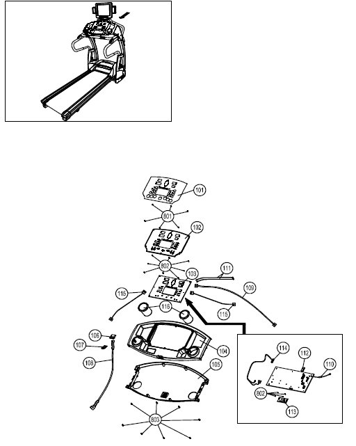
9.45ST-100 Complete Computer Console
| Item No. |
Description |
Qty. |
Part No. |
| 101 |
Overlay |
1 |
9.45ST-101 |
| 102 |
Computer Insert |
1 |
9.45ST-102 |
| 103 |
Console PC Board |
1 |
9.45ST-103 |
| 104 |
Console Housing ���¢�������� Upper |
1 |
9.45ST-104 |
| 105 |
Console Housing ���¢�������� Bottom |
1 |
9.45ST-105 |
| 106 |
Safety Key Base |
1 |
9.45ST-106 |
| 107 |
Safety Key |
1 |
9.45ST-107 |
| 108 |
Safety Key Wire ���¢�������� Upper |
1 |
9.45ST-108 |
| 109 |
Computer Wire ���¢�������� Upper |
1 |
9.45ST-109 |
| 110 |
Computer Ground Wire |
1 |
9.45ST-110 |
| 111 |
Hand Pulse Wire ���¢�������� Upper |
2 |
9.45ST-111 |
| 112 |
E ���¢�������� Prom |
1 |
9.45ST-112 |
| 113 |
Motion Control Board |
1 |
9.45ST-113 |
| 114 |
Motion Control Board Wire |
1 |
9.45ST-114 |
| 115 |
Motion Control Sensor Wire |
2 |
9.45ST-115 |
| 116 |
Water Bottle Holder |
2 |
9.45ST-116 |
9.45ST-200 Complete Handle Bar Components
| Item No. |
Description |
Qty. |
Part No. |
| 201 |
Handle Bar Upright |
2 |
9.45ST-201 |
| 202 |
Handle Bar Upright Foam Grip |
2 |
9.45ST-202 |
| 203 |
Front Handle Bar |
1 |
9.45ST-203 |
| 204 |
Front Handle Bar Foam Grip-Short |
1 |
9.45ST-204 |
| 205 |
Front Handle Bar Foam Grip-Long |
2 |
9.45ST-205 |
| 206 |
Hand Pulse Set |
2 |
9.45ST-206 |
| 207 |
Motion Control |
2 |
9.45ST-207 |
| 208 |
Motion Control Base |
2 |
9.45ST-208 |
9.45ST-300 Complete Upright Components
| Item No. |
Description |
Qty. |
Part No. |
| 301 |
Upright |
2 |
9.45ST-301 |
| 303 |
Upright Cover-LL |
1 |
9.45ST-303 |
| 304 |
Upright Cover-LR |
1 |
9.45ST-304 |
| 305 |
Upright Cover-RL |
1 |
9.45ST-305 |
| 306 |
Upright Cover-RR |
1 |
9.45ST-306 |
| 307 |
Safety Key Wire ���¢�������� Middle |
1 |
9.45ST-307 |
| 308 |
Computer Wire ���¢�������� Upper |
1 |
9.45ST-308 |
| 309 |
Motion Control Sensor Wire - Middle |
2 |
9.45ST-309 |
| 310 |
Adjustable Cylinder |
2 |
9.45ST-310 |
| 311 |
Upright Plastic Shroud ���¢�������� LL |
1 |
9.45ST-311 |
| 312 |
Upright Plastic Shroud ���¢�������� LR |
1 |
9.45ST-312 |
| 313 |
Upright Plastic Shroud ���¢�������� RL |
1 |
9.45ST-313 |
| 314 |
Upright Plastic Shroud ���¢�������� RR |
1 |
9.45ST-314 |
| 315 |
Adjustable Cylinder Cover - Upper |
2 |
9.45ST-315 |
| 318 |
Fixing Inserts |
2 |
9.45ST-318 |
9.45ST-400 Complete Base Frame Components
| Item No. |
Description |
Qty. |
Part No. |
| 401 |
Base Frame |
1 |
9.45ST-401 |
| 402 |
Safety Key Wire ���¢�������� Lower |
1 |
9.45ST-402 |
| 403 |
Computer Wire ���¢��������Lower |
1 |
9.45ST-403 |
| 404 |
Power Switch Plate Cover |
1 |
9.45ST-404 |
| 405 |
Power Switch Plate |
1 |
9.45ST-405 |
| 406 |
Power Breaker |
1 |
9.45ST-406 |
| 407 |
Power Switch |
1 |
9.45ST-407 |
| 411 |
Bushing |
4 |
9.45ST-411 |
| 412 |
Fix Bolt Sets |
2 |
9.45ST-412 |
| 413 |
Front Caster |
2 |
9.45ST-413 |
| 414 |
Rubber Cushion |
2 |
9.45ST-414 |
| 415 |
Level Adjuster |
2 |
9.45ST-415 |
| 416 |
Base Frame End Cap |
2 |
9.45ST-416 |
| 417 |
Cushion |
2 |
9.45ST-417 |
| 426 |
Shock |
1 |
9.45ST-426 |
9.45ST-500 Complete Motor Components
| Item No. |
Description |
Qty. |
Part No. |
| 501 |
Motor Hood |
1 |
9.45ST-501 |
| 502 |
Elevation Motor |
1 |
9.45ST-502 |
| 503 |
Elevation Gear Sleeve |
1 |
9.45ST-503 |
| 504 |
Driving Motor |
1 |
9.45ST-504 |
| 505 |
Motor Holder |
1 |
9.45ST-505 |
| 506 |
Driving Belt |
1 |
9.45ST-506 |
| 507 |
Motor Control Board |
1 |
9.45ST-507 |
| 508 |
Elevation Control Board |
1 |
9.45ST-508 |
| 509 |
Elevation Support Tube |
1 |
9.45ST-509 |
| 510 |
Elevation Support Tube Cover - LEFT |
1 |
9.45ST-510 |
| 511 |
Motor Bottom Cover |
1 |
9.45ST-511 |
| 512 |
Deck Frame Side Cover - LEFT |
1 |
9.45ST-512 |
| 513 |
Plastic Clamp - TOP |
2 |
9.45ST-513 |
| 514 |
Plastic Clamp - BOTTOM |
2 |
9.45ST-514 |
| 515 |
Elevation Support |
2 |
9.45ST-515 |
| 516 |
Deck Rubber Cushion |
2 |
9.45ST-516 |
| 517 |
Rear Vent Cover |
1 |
9.45ST-517 |
| 518 |
Elevation Support Tube Cover - RIGHT |
1 |
9.45ST-518 |
| 519 |
Deck Frame Side Cover ���¢�������� RIGHT |
1 |
9.45ST-519 |
9.45ST-600 Complete Running Deck Components
| Item No. |
Description |
Qty. |
Part No. |
| 601 |
Running Belt |
1 |
9.45ST-601 |
| 602 |
Side Rail |
1 |
9.45ST-602 |
| 603 |
Running Deck |
1 |
9.45ST-603 |
| 604 |
Side Rail End Cap - LEFT |
1 |
9.45ST-604 |
| 605 |
Side Rail End Cap - RIGHT |
1 |
9.45ST-605 |
9.45ST-700 Complete Deck Frame Components
| Item No. |
Description |
Qty. |
Part No. |
| 701 |
Deck Frame |
1 |
9.45ST-701 |
| 702 |
Front Roller Shaft |
1 |
9.45ST-702 |
| 703 |
Front Roller Tube |
1 |
9.45ST-703 |
| 704 |
Roller Bearing 6202 |
4 |
9.45ST-704 |
| 705 |
Rear Roller Shaft |
1 |
9.45ST-705 |
| 706 |
Rear Roller Tube |
1 |
9.45ST-706 |
| 707 |
Running Deck Support Tube |
1 |
9.45ST-707 |
| 708 |
Deck Frame ���¢�������� Rear |
1 |
9.45ST-708 |
| 709 |
Steady Frame |
1 |
9.45ST-709 |
| 413 |
Rear Caster |
2 |
9.45ST-413 |
9.45ST-800 Complete Hardware Pack
| Item No. |
Description |
Qty. |
Part No. |
| 801 |
?6 Ã?Â?Ã?Â?Ã?Â?Ã?Â? 12mm Screws |
10 |
9.45ST-801 |
| 802 |
M4 Ã?Â?Ã?Â?Ã?Â?Ã?Â? 6mm Screws |
12 |
9.45ST-802 |
| 803 |
M8 Ã?Â?Ã?Â?Ã?Â?Ã?Â? 12mm Screws |
8 |
9.45ST-803 |
| 804 |
M8 Ã?Â?Ã?Â?Ã?Â?Ã?Â? 15mm Bolt |
3 |
9.45ST-804 |
| 805 |
M8 Ã?Â?Ã?Â?Ã?Â?Ã?Â? 50mm Bolt |
12 |
9.45ST-805 |
| 806 |
# 8 Ã?Â?Ã?Â?Ã?Â?Ã?Â? 20mm Screw |
20 |
9.45ST-806 |
| 807 |
4 Ã?Â?Ã?Â?Ã?Â?Ã?Â? 15mm Thread Cutting Screw |
19 |
9.45ST-807 |
| 808 |
M5 Ã?Â?Ã?Â?Ã?Â?Ã?Â? 10mm Screws |
2 |
9.45ST-808 |
| 809 |
M8 Ã?Â?Ã?Â?Ã?Â?Ã?Â? 16 Screws |
20 |
9.45ST-809 |
| 813 |
Washer |
4 |
9.45ST-813 |
| 814 |
Nylon Nut |
6 |
9.45ST-814 |
| 816 |
M14 Ã?Â?Ã?Â?Ã?Â?Ã?Â? 90 Screws |
3 |
9.45ST-816 |
| 817 |
Bearing |
4 |
9.45ST-817 |
| 818 |
M10 Ã?Â?Ã?Â?Ã?Â?Ã?Â? 35mm Screws |
10 |
9.45ST-818 |
| 819 |
M8 Ã?Â?Ã?Â?Ã?Â?Ã?Â? 10mm Screws |
7 |
9.45ST-819 |
| 820 |
M8 Ã?Â?Ã?Â?Ã?Â?Ã?Â? 50mm Screws |
2 |
9.45ST-820 |
| 821 |
M10 Ã?Â?Ã?Â?Ã?Â?Ã?Â? 63mm Bolts |
1 |
9.45ST-821 |
| 822 |
Fixed Block |
8 |
9.45ST-822 |
| 823 |
M8 Ã?Â?Ã?Â?Ã?Â?Ã?Â? 120mm Bolts |
1 |
9.45ST-823 |
| 824 |
Plate Washer |
2 |
9.45ST-824 |
| 825 |
Spring |
1 |
9.45ST-825 |
| 826 |
M8 Nylon Nut |
2 |
9.45ST-826 |
| 827 |
M8 Ã?Â?Ã?Â?Ã?Â?Ã?Â? 20mm Screws |
6 |
9.45ST-827 |
| 828 |
Spring Washer |
12 |
9.45ST-828 |
| 829 |
Washer |
2 |
9.45ST-829 |
| 830 |
M10 Ã?Â?Ã?Â?Ã?Â?Ã?Â? 136mm Screws |
1 |
9.45ST-830 |
| 832 |
M8 Ã?Â?Ã?Â?Ã?Â?Ã?Â? 25mm Screws |
8 |
9.45ST-832 |
| 833 |
Hexagon Nut |
10 |
9.45ST-833 |
| 834 |
M6 Ã?Â?Ã?Â?Ã?Â?Ã?Â? 70mm Bolts |
3 |
9.45ST-834 |
| 838 |
M10 Ã?Â?Ã?Â?Ã?Â?Ã?Â? 43mm Bolts |
2 |
9.45ST-838 |
| 839 |
Cushion Pad |
10 |
9.45ST-839 |
| 840 |
M10 Ã?Â?Ã?Â?Ã?Â?Ã?Â? 40mm Screws |
1 |
9.45ST-840 |
| 841 |
M6 Ã?Â?Ã?Â?Ã?Â?Ã?Â? 10mm Screws |
2 |
9.45ST-841 |
| 842 |
M10 Ã?Â?Ã?Â?Ã?Â?Ã?Â? 30mm Allen Head Bolt |
2 |
9.45ST-842 |
| 843 |
M8 Ã?Â?Ã?Â?Ã?Â?Ã?Â? 15mm Allen Head Bolt |
4 |
9.45ST-843 |
| 845 |
13 Ã?Â?Ã?Â?Ã?Â?Ã?Â? 42mm Shaft |
2 |
9.45ST-845 |
| 846 |
#8 Ã?Â?Ã?Â?Ã?Â?Ã?Â? 23mm Washer |
2 |
9.45ST-846 |
9.45ST-100 Complete Computer Console
Item No.
Description
Qty.
Part No.
102
Computer Insert
1
9.45ST-102
103
Console PC Board
1
9.45ST-103
104
Console Housing ���¢�������� Upper
1
9.45ST-104
105
Console Housing ���¢�������� Bottom
1
9.45ST-105
106
Safety Key Base
1
9.45ST-106
107
Safety Key
1
9.45ST-107
108
Safety Key Wire ���¢�������� Upper
1
9.45ST-108
109
Computer Wire ���¢�������� Upper
1
9.45ST-109
110
Computer Ground Wire
1
9.45ST-110
111
Hand Pulse Wire ���¢�������� Upper
2
9.45ST-111
112
E ���¢�������� Prom
1
9.45ST-112
113
Motion Control Board
1
9.45ST-113
114
Motion Control Board Wire
1
9.45ST-114
115
Motion Control Sensor Wire
2
9.45ST-115
116
Water Bottle Holder
2
9.45ST-116
9.45ST-200 Complete Handle Bar Components
Item
Description
Qty.
Part No.
201
Handle Bar Upright
2
9.45ST-201
202
Handle Bar Upright Foam Grip
2
9.45ST-202
203
Front Handle Bar
1
9.45ST-203
204
Front Handle Bar Foam Grip-Short
1
9.45ST-204
205
Front Handle Bar Foam Grip-Long
2
9.45ST-205
206
Hand Pulse Set
2
9.45ST-206
207
Motion Control
2
9.45ST-207
208
Motion Control Base
2
9.45ST-208
9.45ST-300 Complete Upright Components
Item
Description
Qty.
Part No.
303
Upright Cover-LL
1
9.45ST-303
304
Upright Cover-LR
1
9.45ST-304
305
Upright Cover-RL
1
9.45ST-305
306
Upright Cover-RR
1
9.45ST-306
307
Safety Key Wire ���¢�������� Middle
1
9.45ST-307
308
Computer Wire ���¢�������� Upper
1
9.45ST-308
309
Motion Control Sensor Wire - Middle
2
9.45ST-309
310
Adjustable Cylinder
2
9.45ST-310
311
Upright Plastic Shroud ���¢�������� LL
1
9.45ST-311
312
Upright Plastic Shroud ���¢�������� LR
1
9.45ST-312
313
Upright Plastic Shroud ���¢�������� RL
1
9.45ST-313
314
Upright Plastic Shroud ���¢�������� RR
1
9.45ST-314
315
Adjustable Cylinder Cover - Upper
1
9.45ST-315
318
Fixing Inserts
1
9.45ST-318
9.45ST-400 Complete Base Frame Components
Item
Description
Qty.
Part No.
401
Base Frame
1
9.45ST-401
402
Safety Key Wire ���¢�������� Lower
1
9.45ST-402
403
Computer Wire ���¢��������Lower
1
9.45ST-403
404
Power Switch Plate Cover
1
9.45ST-404
405
Power Switch Plate
1
9.45ST-405
406
Power Breaker
1
9.45ST-406
407
Power Switch
1
9.45ST-407
412
Fix Bolt Sets
2
9.45ST-412
413
Front Caster
2
9.45ST-413
414
Rubber Cushion
2
9.45ST-414
415
Level Adjuster
2
9.45ST-415
416
Base Frame End Cap
2
9.45ST-416
9.45ST-500 Complete Motor Components
Item
Description
Qty.
Part No.
501
Motor Hood
1
9.45ST-501
502
Elevation Motor
1
9.45ST-502
503
Elevation Gear Sleeve
1
9.45ST-503
504
Driving Motor
1
9.45ST-504
505
Motor Holder
1
9.45ST-505
506
Driving Belt
1
9.45ST-506
507
Motor Control Board
1
9.45ST-507
508
Elevation Control Board
1
9.45ST-508
509
Elevation Support Tube
1
9.45ST-509
510
Elevation Support Tube Cover - LEFT
1
9.45ST-510
511
Motor Bottom Cover
1
9.45ST-511
512
Deck Frame Side Cover - LEFT
1
9.45ST-512
513
Plastic Clamp - TOP
2
9.45ST-513
514
Plastic Clamp - BOTTOM
2
9.45ST-514
515
Elevation Support
2
9.45ST-515
516
Deck Rubber Cushion
2
9.45ST-516
517
Rear Vent Cover
1
9.45ST-517
518
Elevation Support Tube Cover - RIGHT
1
9.45ST-518
519
Deck Frame Side Cover ���¢�������� RIGHT
1
9.45ST-519
9.45ST-600 Complete Running Deck Components
Item
Description
Qty.
Part No.
601
Running Belt
1
9.45ST-601
602
Side Rail
2
9.45ST-602
603
Running Deck
1
9.45ST-603
604
Side Rail End Cap - LEFT
1
9.45ST-604
605
Side Rail End Cap - RIGHT
1
9.45ST-605
9.45ST-700 Complete Deck Frame Components
Item
Description
Qty.
Part No.
701
Deck Frame
1
9.35HR-701
702
Front Roller Shaft
1
9.35HR-702
703
Front Roller Tube
1
9.35HR-703
704
Roller Bearing 6202
4
9.35HR-704
705
Rear Roller Shaft
1
9.35HR-705
706
Rear Roller Tube
1
9.35HR-706
707
Running Deck Support Tube
1
9.35HR-707
708
Deck Frame ���¢�������� Rear
1
9.35HR-708
709
Steady Frame
1
9.35HR-709
413
Rear Caster
2
9.35HR-413
9.45ST-800 Complete Hardware Pack
Item
Description
Qty.
Part No.
801
?6 Ã?Â?Ã?Â?Ã?Â?Ã?Â? 12mm Screws
10
9.45ST-801
802
M4 Ã?Â?Ã?Â?Ã?Â?Ã?Â? 6mm Screws
12
9.45ST-802
803
M8 Ã?Â?Ã?Â?Ã?Â?Ã?Â? 12mm Screws
8
9.45ST-803
804
M8 Ã?Â?Ã?Â?Ã?Â?Ã?Â? 15mm Bolt
3
9.45ST-804
805
M8 Ã?Â?Ã?Â?Ã?Â?Ã?Â? 50mm Bolt
12
9.45ST-805
806
# 8 Ã?Â?Ã?Â?Ã?Â?Ã?Â? 20mm Screw
20
9.45ST-806
807
4 Ã?Â?Ã?Â?Ã?Â?Ã?Â? 15mm Thread Cutting Screw
19
9.45ST-807
808
M5 Ã?Â?Ã?Â?Ã?Â?Ã?Â? 10mm Screws
2
9.45ST-808
809
M8 Ã?Â?Ã?Â?Ã?Â?Ã?Â? 16 Screws
20
9.45ST-809
814
Nylon Nut
6
9.45ST-814
816
M14 Ã?Â?Ã?Â?Ã?Â?Ã?Â? 90 Screws
3
9.45ST-816
818
M10 Ã?Â?Ã?Â?Ã?Â?Ã?Â? 35mm Screws
10
9.45ST-818
819
M8 Ã?Â?Ã?Â?Ã?Â?Ã?Â? 10mm Screws
7
9.45ST-819
820
M8 Ã?Â?Ã?Â?Ã?Â?Ã?Â? 50mm Screws
2
9.45ST-820
821
M10 Ã?Â?Ã?Â?Ã?Â?Ã?Â? 63mm Bolts
1
9.45ST-821
822
Fixed Block
8
9.45ST-822
823
M8 Ã?Â?Ã?Â?Ã?Â?Ã?Â? 120mm Bolts
1
9.45ST-823
824
Plate Washer
2
9.45ST-824
826
M8 Nylon Nut
2
9.45ST-826
827
M8 Ã?Â?Ã?Â?Ã?Â?Ã?Â? 20mm Screws
6
9.45ST-827
828
Spring Washer
12
9.45ST-828
830
M10 Ã?Â?Ã?Â?Ã?Â?Ã?Â? 136mm Screws
1
9.45ST-830
832
M8 Ã?Â?Ã?Â?Ã?Â?Ã?Â? 25mm Screws
8
9.45ST-832
833
Hexagon Nut
10
9.45ST-833
834
M6 Ã?Â?Ã?Â?Ã?Â?Ã?Â? 70mm Bolts
3
9.45ST-834
838
M10 Ã?Â?Ã?Â?Ã?Â?Ã?Â? 43mm Bolts
2
9.45ST-838
839
Cushion Pad
10
9.45ST-839
840
M10 Ã?Â?Ã?Â?Ã?Â?Ã?Â? 40mm Screws
1
9.45ST-840
841
M6 Ã?Â?Ã?Â?Ã?Â?Ã?Â? 10mm Screws
2
9.45ST-841
842
M10 Ã?Â?Ã?Â?Ã?Â?Ã?Â? 30mm Allen Head Bolt
2
9.45ST-842
843
M8 Ã?Â?Ã?Â?Ã?Â?Ã?Â? 15mm Allen Head Bolt
4
9.45ST-843
845
13 Ã?Â?Ã?Â?Ã?Â?Ã?Â? 42mm Shaft
2
9.45ST-845
846
#8 Ã?Â?Ã?Â?Ã?Â?Ã?Â? 23mm Washer
2
9.45ST-846
9.45TV Parts List
9.45TV-100 Complete Computer Console
| Item No. |
Description |
Qty. |
Part No. |
| 101 |
Overlay |
1 |
9.45TV-101 |
| 102 |
Computer Insert |
1 |
9.45TV-102 |
| 104 |
Console Housing ���¢�������� Upper |
1 |
9.45TV-104 |
| 105 |
Console Housing ���¢�������� Bottom |
1 |
9.45TV-105 |
| 106 |
Safety Key Base |
1 |
9.45TV-106 |
| 107 |
Safety Key |
1 |
9.45TV-107 |
| 108 |
Safety Key Wire ���¢�������� Upper |
1 |
9.45TV-108 |
| 109 |
Computer Wire ���¢�������� Upper |
1 |
9.45TV-109 |
| 110 |
Computer Ground Wire |
1 |
9.45TV-110 |
| 111 |
Hand Pulse Wire ���¢�������� Upper |
2 |
9.45TV-111 |
| 112 |
E ���¢�������� Prom |
2 |
9.45TV-112 |
| 113 |
Motion Control Board |
1 |
9.45TV-113 |
| 114 |
Motion Control Board Wire |
1 |
9.45TV-114 |
| 115 |
Motion Control Sensor Wire |
2 |
9.45TV-115 |
| 116 |
Water Bottle Holder |
2 |
9.45TV-116 |
9.45TV-200 Complete Handle Bar Components
| Item No. |
Description |
Qty. |
Part No. |
| 201 |
Handle Bar Upright |
2 |
9.45TV-201 |
| 202 |
Handle Bar Upright Foam Grip |
2 |
9.45TV-202 |
| 203 |
Front Handle Bar |
1 |
9.45TV-203 |
| 204 |
Front Handle Bar Foam Grip-Short |
1 |
9.45TV-204 |
| 205 |
Front Handle Bar Foam Grip-Long |
2 |
9.45TV-205 |
| 206 |
Hand Pulse Set |
2 |
9.45TV-206 |
| 207 |
Motion Control |
2 |
9.45TV-207 |
| 208 |
Motion Control Base |
2 |
9.45TV-208 |
9.45TV-300 Complete Upright Components
| Item No. |
Description |
Qty. |
Part No. |
| 301 |
Upright |
2 |
9.45TV-301 |
| 303 |
Upright Cover-LL |
1 |
9.45TV-303 |
| 304 |
Upright Cover-LR |
1 |
9.45TV-304 |
| 305 |
Upright Cover-RL |
1 |
9.45TV-305 |
| 306 |
Upright Cover-RR |
1 |
9.45TV-306 |
| 307 |
Safety Key Wire ���¢�������� Middle |
1 |
9.45TV-307 |
| 308 |
Computer Wire ���¢�������� Upper |
1 |
9.45TV-308 |
| 309 |
Motion Control Sensor Wire - Middle |
2 |
9.45TV-309 |
| 310 |
Adjustable Cylinder |
2 |
9.45TV-310 |
| 311 |
Upright Plastic Shroud ���¢�������� LL |
1 |
9.45TV-311 |
| 312 |
Upright Plastic Shroud ���¢�������� LR |
1 |
9.45TV-312 |
| 313 |
Upright Plastic Shroud ���¢�������� RL |
1 |
9.45TV-313 |
| 314 |
Upright Plastic Shroud ���¢�������� RR |
1 |
9.45TV-314 |
| 315 |
Adjustable Cylinder Cover - Upper |
2 |
9.45TV-315 |
| 318 |
Fixing Inserts |
2 |
9.45TV-318 |
9.45TV-400 Complete Base Frame Components
| Item No. |
Description |
Qty. |
Part No. |
| 401 |
Base Frame |
1 |
9.45TV-401 |
| 402 |
Safety Key Wire ���¢�������� Lower |
1 |
9.45TV-402 |
| 403 |
Computer Wire ���¢��������Lower |
1 |
9.45TV-403 |
| 404 |
Power Switch Plate Cover |
1 |
9.45TV-404 |
| 405 |
Power Switch Plate |
1 |
9.45TV-405 |
| 406 |
Power Breaker |
1 |
9.45TV-406 |
| 407 |
Power Switch |
1 |
9.45TV-407 |
| 411 |
Bushing |
4 |
9.45TV-411 |
| 412 |
Fix Bolt Sets |
2 |
9.45TV-412 |
| 413 |
Front Caster |
2 |
9.45TV-413 |
| 414 |
Rubber Cushion |
2 |
9.45TV-414 |
| 415 |
Level Adjuster |
2 |
9.45TV-415 |
| 416 |
Base Frame End Cap |
2 |
9.45TV-416 |
| 417 |
Cushion |
2 |
9.45TV-417 |
| 425 |
I/O Console |
1 |
9.45TV-425 |
| 426 |
Shock |
1 |
9.45TV-426 |
9.45TV-500 Complete Motor Components
| Item No. |
Description |
Qty. |
Part No. |
| 501 |
Motor Hood |
1 |
9.45TV-501 |
| 502 |
Elevation Motor |
1 |
9.45TV-502 |
| 503 |
Elevation Gear Sleeve |
1 |
9.45TV-503 |
| 504 |
Driving Motor |
1 |
9.45TV-504 |
| 505 |
Motor Holder |
1 |
9.45TV-505 |
| 506 |
Driving Belt |
1 |
9.45TV-506 |
| 507 |
Motor Control Board |
1 |
9.45TV-507 |
| 508 |
Elevation Control Board |
1 |
9.45TV-508 |
| 509 |
Elevation Support Tube |
1 |
9.45TV-509 |
| 510 |
Elevation Support Tube Cover - LEFT |
1 |
9.45TV-510 |
| 511 |
Motor Bottom Cover |
1 |
9.45TV-511 |
| 512 |
Deck Frame Side Cover - LEFT |
1 |
9.45TV-512 |
| 513 |
Plastic Clamp - TOP |
2 |
9.45TV-513 |
| 514 |
Plastic Clamp - BOTTOM |
2 |
9.45TV-514 |
| 515 |
Elevation Support |
2 |
9.45TV-515 |
| 516 |
Deck Rubber Cushion |
2 |
9.45TV-516 |
| 517 |
Rear Vent Cover |
1 |
9.45TV-517 |
| 518 |
Elevation Support Tube Cover - RIGHT |
1 |
9.45TV-518 |
| 519 |
Deck Frame Side Cover ���¢�������� RIGHT |
1 |
9.45TV-519 |
9.45TV-600 Complete Running Deck Components
| Item No. |
Description |
Qty. |
Part No. |
| 601 |
Running Belt |
1 |
9.45TV-601 |
| 602 |
Side Rail |
2 |
9.45TV-602 |
| 603 |
Running Deck |
1 |
9.45TV-603 |
| 604 |
Side Rail End Cap - LEFT |
1 |
9.45TV-604 |
| 605 |
Side Rail End Cap - RIGHT |
1 |
9.45TV-605 |
9.45TV-700 Complete Deck Frame Components
| Item No. |
Description |
Qty. |
Part No. |
| 701 |
Deck Frame |
1 |
9.45TV-701 |
| 702 |
Front Roller Shaft |
1 |
9.45TV-702 |
| 703 |
Front Roller Tube |
1 |
9.45TV-703 |
| 704 |
Roller Bearing 6202 |
4 |
9.45TV-704 |
| 705 |
Rear Roller Shaft |
1 |
9.45TV-705 |
| 706 |
Rear Roller Tube |
1 |
9.45TV-706 |
| 707 |
Running Deck Support Tube |
1 |
9.45TV-707 |
| 708 |
Deck Frame ���¢�������� Rear |
1 |
9.45TV-708 |
| 709 |
Steady Frame |
1 |
9.45TV-709 |
| 413 |
Rear Caster |
2 |
9.45TV-413 |
9.45TV-800 Complete Hardware Pack
| Item No. |
Description |
Qty. |
Part No. |
| 801 |
?6 Ã?Â?Ã?Â?Ã?Â?Ã?Â? 12mm Screws |
10 |
9.45TV-801 |
| 802 |
M4 Ã?Â?Ã?Â?Ã?Â?Ã?Â? 6mm Screws |
12 |
9.45TV-802 |
| 803 |
M8 Ã?Â?Ã?Â?Ã?Â?Ã?Â? 12mm Screws |
8 |
9.45TV-803 |
| 804 |
M8 Ã?Â?Ã?Â?Ã?Â?Ã?Â? 15mm Bolt |
3 |
9.45TV-804 |
| 805 |
M8 Ã?Â?Ã?Â?Ã?Â?Ã?Â? 50mm Bolt |
16 |
9.45TV-805 |
| 806 |
# 8 Ã?Â?Ã?Â?Ã?Â?Ã?Â? 20mm Screw |
20 |
9.45TV-806 |
| 807 |
4 Ã?Â?Ã?Â?Ã?Â?Ã?Â? 15mm Thread Cutting Screw |
19 |
9.45TV-807 |
| 808 |
M5 Ã?Â?Ã?Â?Ã?Â?Ã?Â? 10mm Screws |
4 |
9.45TV-808 |
| 809 |
M8 Ã?Â?Ã?Â?Ã?Â?Ã?Â? 16 Screws |
20 |
9.45TV-809 |
| 813 |
Washer |
4 |
9.45TV-813 |
| 814 |
Nylon Nut |
6 |
9.45TV-814 |
| 816 |
M14 Ã?Â?Ã?Â?Ã?Â?Ã?Â? 90 Screws |
3 |
9.45TV-816 |
| 817 |
Bearing |
4 |
9.45TV-817 |
| 818 |
M10 Ã?Â?Ã?Â?Ã?Â?Ã?Â? 35mm Screws |
10 |
9.45TV-818 |
| 819 |
M8 Ã?Â?Ã?Â?Ã?Â?Ã?Â? 10mm Screws |
7 |
9.45TV-819 |
| 820 |
M8 Ã?Â?Ã?Â?Ã?Â?Ã?Â? 50mm Screws |
2 |
9.45TV-820 |
| 821 |
M10 Ã?Â?Ã?Â?Ã?Â?Ã?Â? 63mm Bolts |
1 |
9.45TV-821 |
| 822 |
Fixed Block |
8 |
9.45TV-822 |
| 823 |
M8 Ã?Â?Ã?Â?Ã?Â?Ã?Â? 120mm Bolts |
1 |
9.45TV-823 |
| 824 |
Plate Washer |
2 |
9.45TV-824 |
| 825 |
Spring |
1 |
9.45TV-825 |
| 826 |
M8 Nylon Nut |
2 |
9.45TV-826 |
| 827 |
M8 Ã?Â?Ã?Â?Ã?Â?Ã?Â? 20mm Screws |
8 |
9.45TV-827 |
| 828 |
Spring Washer |
12 |
9.45TV-828 |
| 829 |
Washer |
2 |
9.45TV-829 |
| 830 |
M10 Ã?Â?Ã?Â?Ã?Â?Ã?Â? 136mm Screws |
1 |
9.45TV-830 |
| 832 |
M8 Ã?Â?Ã?Â?Ã?Â?Ã?Â? 25mm Screws |
8 |
9.45TV-832 |
| 833 |
Hexagon Nut |
10 |
9.45TV-833 |
| 834 |
M6 Ã?Â?Ã?Â?Ã?Â?Ã?Â? 70mm Bolts |
3 |
9.45TV-834 |
| 838 |
M10 Ã?Â?Ã?Â?Ã?Â?Ã?Â? 43mm Bolts |
2 |
9.45TV-838 |
| 839 |
Cushion Pad |
10 |
9.45TV-839 |
| 840 |
M10 Ã?Â?Ã?Â?Ã?Â?Ã?Â? 40mm Screws |
1 |
9.45TV-840 |
| 841 |
M6 Ã?Â?Ã?Â?Ã?Â?Ã?Â? 10mm Screws |
2 |
9.45TV-841 |
| 842 |
M10 Ã?Â?Ã?Â?Ã?Â?Ã?Â? 30mm Allen Head Bolt |
2 |
9.45TV-842 |
| 843 |
M8 Ã?Â?Ã?Â?Ã?Â?Ã?Â? 15mm Allen Head Bolt |
4 |
9.45TV-843 |
| 845 |
13 Ã?Â?Ã?Â?Ã?Â?Ã?Â? 42mm Shaft |
2 |
9.45TV-845 |
| 846 |
#8 Ã?Â?Ã?Â?Ã?Â?Ã?Â? 23mm Washer |
2 |
9.45TV-846 |
| 847 |
M5 x 12mm Flat Head Bolt |
2 |
9.45TV-847 |
9.45TV-100 Complete Computer Console
Item No.
Description
Qty.
Part No.
102
Computer Insert
1
9.45TV-102
103
Console PC Board
1
9.45TV-103
104
Console Housing ���¢�������� Upper
1
9.45TV-104
105
Console Housing ���¢�������� Bottom
1
9.45TV-105
106
Safety Key Base
1
9.45TV-106
107
Safety Key
1
9.45TV-106
108
Safety Key Wire ���¢�������� Upper
1
9.45TV-108
109
Computer Wire ���¢�������� Upper
1
9.45TV-109
110
Computer Ground Wire
1
9.45TV-110
111
Hand Pulse Wire ���¢�������� Upper
2
9.45TV-111
112
E ���¢�������� Prom
2
9.45TV-112
113
Motion Control Board
2
9.45TV-113
114
Motion Control Board Wire
1
9.45TV-114
115
Motion Control Sensor Wire
1
9.45TV-115
116
Water Bottle Holder
1
9.45TV-116
9.45TV-200 Complete Handle Bar Components
Item
Description
Qty.
Part No.
201
Handle Bar Upright
2
9.45TV-201
202
Handle Bar Upright Foam Grip
2
9.45TV-202
203
Front Handle Bar
1
9.45TV-203
204
Front Handle Bar Foam Grip-Short
1
9.45TV-204
205
Front Handle Bar Foam Grip-Long
2
9.45TV-205
206
Hand Pulse Set
2
9.45TV-206
207
Motion Control
2
9.45TV-207
208
Motion Control Base
2
9.45TV-208
9.45TV-300 Complete Upright Components
Item
Description
Qty.
Part No.
303
Upright Cover-LL
1
9.45TV-303
304
Upright Cover-LR
1
9.45TV-304
305
Upright Cover-RL
1
9.45TV-305
306
Upright Cover-RR
1
9.45TV-306
307
Safety Key Wire ���¢�������� Middle
1
9.45TV-307
308
Computer Wire ���¢�������� Upper
1
9.45TV-308
309
Motion Control Sensor Wire - Middle
2
9.45TV-309
310
Adjustable Cylinder
2
9.45TV-310
311
Upright Plastic Shroud ���¢�������� LL
1
9.45TV-311
312
Upright Plastic Shroud ���¢�������� LR
1
9.45TV-312
313
Upright Plastic Shroud ���¢�������� RL
1
9.45TV-313
314
Upright Plastic Shroud ���¢�������� RR
1
9.45TV-314
315
Adjustable Cylinder Cover - Upper
2
9.45TV-315
318
Fixing Inserts
2
9.45TV-318
9.45TV-400 Complete Base Frame Components
Item
Description
Qty.
Part No.
401
Base Frame
1
9.45TV-401
402
Safety Key Wire ���¢�������� Lower
1
9.45TV-402
403
Computer Wire ���¢��������Lower
1
9.45TV-403
404
Power Switch Plate Cover
1
9.45TV-404
405
Power Switch Plate
1
9.45TV-405
406
Power Breaker
1
9.45TV-406
407
Power Switch
1
9.45TV-407
412
Fix Bolt Sets
2
9.45TV-412
413
Front Caster
2
9.45TV-413
414
Rubber Cushion
2
9.45TV-414
415
Level Adjuster
2
9.45TV-415
416
Base Frame End Cap
2
9.45TV-416
425
I/O Console
1
9.45TV-425
9.45TV-500 Complete Motor Components
Item
Description
Qty.
Part No.
501
Motor Hood
1
9.45TV-501
502
Elevation Motor
1
9.45TV-502
503
Elevation Gear Sleeve
1
9.45TV-503
504
Driving Motor
1
9.45TV-504
505
Motor Holder
1
9.45TV-505
506
Driving Belt
1
9.45TV-506
507
Motor Control Board
1
9.45TV-507
508
Elevation Control Board
1
9.45TV-508
509
Elevation Support Tube
1
9.45TV-509
510
Elevation Support Tube Cover - LEFT
1
9.45TV-510
511
Motor Bottom Cover
1
9.45TV-511
512
Deck Frame Side Cover - LEFT
1
9.45TV-512
513
Plastic Clamp - TOP
2
9.45TV-513
514
Plastic Clamp - BOTTOM
2
9.45TV-514
515
Elevation Support
2
9.45TV-515
516
Deck Rubber Cushion
2
9.45TV-516
517
Rear Vent Cover
1
9.45TV-517
518
Elevation Support Tube Cover - RIGHT
1
9.45TV-518
519
Deck Frame Side Cover ���¢�������� RIGHT
1
9.45TV-519
9.45TV-600 Complete Running Deck Components
Item
Description
Qty.
Part No.
601
Running Belt
1
9.45TV-601
602
Side Rail
2
9.45TV-602
603
Running Deck
1
9.45TV-603
604
Side Rail End Cap - LEFT
1
9.45TV-604
605
Side Rail End Cap - RIGHT
1
9.45TV-606
9.45TV-700 Complete Deck Frame Components
Item
Description
Qty.
Part No.
701
Deck Frame
1
9.45TV-701
702
Front Roller Shaft
1
9.45TV-702
703
Front Roller Tube
1
9.45TV-703
704
Roller Bearing 6202
4
9.45TV-704
705
Rear Roller Shaft
1
9.45TV-705
706
Rear Roller Tube
1
9.45TV-706
707
Running Deck Support Tube
1
9.45TV-707
708
Deck Frame ���¢�������� Rear
1
9.45TV-708
709
Steady Frame
1
9.45TV-709
413
Rear Caster
2
9.45TV-413
9.45TV-800 Complete Hardware Pack
Item
Description
Qty.
Part No.
801
?6 Ã?Â?Ã?Â?Ã?Â?Ã?Â? 12mm Screws
10
9.45TV-801
802
M4 Ã?Â?Ã?Â?Ã?Â?Ã?Â? 6mm Screws
12
9.45TV-802
803
M8 Ã?Â?Ã?Â?Ã?Â?Ã?Â? 12mm Screws
8
9.45TV-803
804
M8 Ã?Â?Ã?Â?Ã?Â?Ã?Â? 15mm Bolt
3
9.45TV-804
805
M8 Ã?Â?Ã?Â?Ã?Â?Ã?Â? 50mm Bolt
16
9.45TV-805
806
# 8 Ã?Â?Ã?Â?Ã?Â?Ã?Â? 20mm Screw
20
9.45TV-806
807
4 Ã?Â?Ã?Â?Ã?Â?Ã?Â? 15mm Thread Cutting Screw
19
9.45TV-807
808
M5 Ã?Â?Ã?Â?Ã?Â?Ã?Â? 10mm Screws
4
9.45TV-808
809
M8 Ã?Â?Ã?Â?Ã?Â?Ã?Â? 16 Screws
20
9.45TV-809
814
Nylon Nut
6
9.45TV-814
816
M14 Ã?Â?Ã?Â?Ã?Â?Ã?Â? 90 Screws
3
9.45TV-816
818
M10 Ã?Â?Ã?Â?Ã?Â?Ã?Â? 35mm Screws
10
9.45TV-818
819
M8 Ã?Â?Ã?Â?Ã?Â?Ã?Â? 10mm Screws
7
9.45TV-819
820
M8 Ã?Â?Ã?Â?Ã?Â?Ã?Â? 50mm Screws
2
9.45TV-820
821
M10 Ã?Â?Ã?Â?Ã?Â?Ã?Â? 63mm Bolts
1
9.45TV-821
822
Fixed Block
8
9.45TV-822
823
M8 Ã?Â?Ã?Â?Ã?Â?Ã?Â? 120mm Bolts
1
9.45TV-823
824
Plate Washer
2
9.45TV-824
826
M8 Nylon Nut
2
9.45TV-826
827
M8 Ã?Â?Ã?Â?Ã?Â?Ã?Â? 20mm Screwst
6
9.45TV-827
828
Spring Washer
12
9.45TV-828
830
M10 Ã?Â?Ã?Â?Ã?Â?Ã?Â? 136mm Screws
1
9.45TV-830
832
M8 Ã?Â?Ã?Â?Ã?Â?Ã?Â? 25mm Screws
8
9.45TV-832
833
Hexagon Nut
10
9.45TV-833
834
M6 Ã?Â?Ã?Â?Ã?Â?Ã?Â? 70mm Bolts
3
9.45TV-834
838
M10 Ã?Â?Ã?Â?Ã?Â?Ã?Â? 43mm Bolts
2
9.45TV-838
839
Cushion Pad
10
9.45TV-839
840
M10 Ã?Â?Ã?Â?Ã?Â?Ã?Â? 40mm Screws
1
9.45TV-840
841
M6 Ã?Â?Ã?Â?Ã?Â?Ã?Â? 10mm Screws
2
9.45TV-841
842
M10 Ã?Â?Ã?Â?Ã?Â?Ã?Â? 30mm Allen Head Bolt
2
9.45TV-842
843
M8 Ã?Â?Ã?Â?Ã?Â?Ã?Â? 15mm Allen Head Bolt
24
9.45TV-843
845
13 Ã?Â?Ã?Â?Ã?Â?Ã?Â? 42mm Shaft
2
9.45TV-845
846
#8 Ã?Â?Ã?Â?Ã?Â?Ã?Â? 23mm Washer
2
9.45TV-846
847
M5 x 12mm Flat Head Bolt
2
9.45TV-847
Tools required for service procedure
1.Digital display multi meter
2.17mm wrench 2pcs
3.13mm wrench
4.10mm wrench
5.Phillip screw driver
6.5mm Allen wrench
7.6mm Allen wrench
8.8mm Allen wrench
9.5mm Allen wrench with T hand bar
10.6mm Allen wrench with T hand bar
11.Long nose plier
Remove the motor hood
Step 1: Use Phillip screw driver to open 3 bolts and left, right side on bottom motor hood.
Step 2: Use Phillip screw driver to open near both side rails 2 bolts on top motor hood, then move up the motor hood.
Remove the drive motor
Step 1: Follow remove the motor instruction to remove the motor hood.
Step 2: Use 17mm wrench to open bracket tension nut and remove spacer and PU spacer or tension spring. Then remove the motor belt from motor fly wheel.
Step 3: Use 2pcs 17mm wrench to open bracket shaft and nut from main frame.
Step 4: Then use 5mm Allen wrench to open 2 bolts and bracket from motor..
Remove the elevation motor
Step 1: Follow remove the motor instruction to remove the motor hood.
Step 2: Use 17mm wrench to open the nut and remove bolt, and lift up elevation motor nut.
Step 3: Use 17mm wrench and 6mm Allen wrench to open the nut and bolt from main frame front.
Step 4: Then remove elevation motor set.
Remove side rail
Step 1: Follow remove the motor instruction to remove the motor hood.
Step 2: Use Phillip screw driver to open both side end plastic cover.
Step 3: First use 17mm wrench to loose 8 nuts under run desk, then slip out both side rail.
Remove front and rear roller
Step 1: Follow remove the motor instruction to remove the motor hood.
Step 2: Use 5mm Allen wrench to open front roller bolt from front roller holder at left main frame, then remove front roller.
Step 3: Use 5mm Allen wrench to open rear roller 2 bolts from rear roller holder at rear main frame, then remove rear roller.
Remove run desk and run belt
Step 1: Follow remove the motor instruction to remove the motor hood.
Step 2: Follow remove side rail instruction to remove both side rail.
Step 3: Use 5mm Allen wrench to open fix run desk 8 bolt then remove run desk and run belt.
Trouble Shooting
CONSOLE SHOW "Err 2" WHILE TURN POWER ON
The console only one error code and display "Err 2", when replace a new console and switch power on and insert safety key, console will show "Err 2" for 3 sec. then return power status.
If console appear "Err 2", mean must do calibration speed and incline, when finished both calibration procedure, "Err 2" will disappear.
The calibration speed and incline procedure to reference SERVICE SETTING page.
NO DISPLAY REPAIR
NO BELT MOVEMENT REPAIR
ELEVATION MALFUNCTION
HEART RATE(HR) NOT FUNCTIONING/ ERRATIC READING
MOTION CONTROL (MC) MALFUNCTION FOR
Running belt not at central:
The running belt has been properly adjusted at the factory. However transportation, uneven flooring or other unpredicted reasons could cause the belt to shift off center resulting in the belt rubbing with the plastic side rail or end caps and possibly causing damage. To adjust the belt back to it's proper position please follow the directions below:
1.If your belt tends to walk to the right, rotate the right tension bolt clockwise. We recommend adjustments of 1/4 turn at a time, and follow with a test. If your belt continues to walk to the right, simply adjust the left belt tension bolt by turning it �������¼ turn counterclockwise, and follow with a test.
2.If your belt tends to walk to the left, rotate the left tension bolt clockwise 1/4 turn at a time, and follow with a test. If the belt continues to walk to the left, simply adjust the right tension bolt counterclockwise.
3.If your belt appears to be loose, simply tighten both bolts evenly 1/4 turn. If it appears tight, simply loosen both bolts evenly 1/4 turn.
Running belt slip:
The running belt may become loose and slip on the drive roller with each foot plant, If it does, use a 5mm T-bar to turn each bolt �������½ turn clockwise. Be sure to adjust each bolt equally on each side.
Turn the power on and press START button.
Press the SPEED UP button to bring the speed up to 4~5mph(6.4~8kph). Allow the treadmill to run for a minute.
Observe the belt to be sure it stays centered. If not centered follow ADJUST BELT TO
CENTER to procedure.
Walk on the belt to see if it still slips. If it does restart this procedure from head again.
Service Setting
Enter the service Engineer Mode
Switch the power on, press and hold INCLINE UP and DONW and STOP/ENTER 3 buttons then insert the safety key to enter the ENGINEER MODE. Time/Distance display shows "1" and blinking.
Set and display the manufacture date and software version
Press START button, Time/Distance display shows the manufacture YEAR, Heart Rate display shows manufacture MONTH, Calories display shows manufacture DATE. Speed display shows software version. The service engineer can adjust the manufacture date by pressing Incline Up and Down button follow the blinking display then press Enter after each adjustment to record the service date if necessary. After all the adjustment done, press Enter again to exit the Engineer Mode.
Incline Calibration
Enter Engineer mode.
Press Incline Up and Down button till the Time/Distance display shows "2" to enter the Incline Calibration Procedure.
Incline Level display shows "0". Press Incline up and Down button to bring the deck to horizontal position then press STOP/ENTER button to set the L0 level.
After set the L0 level, Incline Level display shows "15" and the treadmill will start incline. Wait till the treadmill stop at the highest position then press STOP/ENTER twice to set the L15 level and exit the engineer mode.
Speed Calibration
Enter Engineer mode.
Press Incline Up and Down button till the Time/Distance display shows "3" to enter the Speed Calibration Procedure.
Speed display shows "0.5"mph or "0.8"kph. Press Speed Up and Down button to adjust the actual speed and measure the belt speed by speed meter then press STOP/ENTER button to set the lowest speed.
After set the lowest speed, Speed display shows "10"mph or "16"kph then treadmill speed will start increase. Wait till treadmill stop increase the speed, measure the belt speed by speed meter and press Speed Up and Down to adjust the actual speed then press STOP/ENTER button twice to exit the Engineer mode.
SLEEP / DISPLAY Mode
When the power is ON the computer will automatically enter SLEEP MODE if it is left idle for 3 minutes without receiving any input. Press any button to return to POWER ON status when the computer is in the SLEEP MODE.
To cancel the SLEEP MODE feature using the DISPLAY MODE and always keep the console display on, pull out the safety key, press and hold the SPEED UP and DOWN buttons, insert the safety key to power on the treadmill. After one short beep sound the TIME LED window will show "ON" (SLEEP MODE feature on) or "OFF" (SLEEP MODE feature off). Press the INCLINE UP and DOWN buttons to switch between "ON" and "OFF" then press STOP/ENTER to save the setting and return to POWER ON mode.
Set sound on/off
Power on and pull out the safety key, press and hold the SPEED UP and DOWN buttons, insert the safety key to power on the treadmill. After one short beep sound the PULSE/INCLINE level display window show "1" and blinking. Press the INCLINE UP and DOWN buttons to select show "2" then press START button, computer will show "ON" or "OFF", press INCLINE UP and DOWN to select between on/off then press STOP/ENTER button twice return power status.
Check and reset maintain mileage
Computer can display service maintain used mileage for service technical engineer check, this maintain mileage for cycle every 700km(436ml) to remind unit owner to maintain treadmill on regular time. when showing maintain mileage can press SPEED DOWN button to reset.
Power switch on and press SPEED UP and DOWN button and hold them then insert safety key. Press INCLINE UP and DOWN button to select PULSE/INCLINE level display window show "3", then press START button, computer will display maintain mileage, press STOP button can reset maintain mileage, last press ENTER button twice return to power on status.
Display total used mileage
Power switch on and press SPEED UP and DOWN button and hold them then insert safety key. Press INCLINE UP and DOWN button to select PULSE/INCLINE level display window show "4", then press START button, computer will display total used mileage, press ENTER button twice return to power on status.
Display total used hours
Power switch on and press SPEED UP and DOWN button and hold them then insert safety key. Press INCLINE UP and DOWN button to select PULSE/INCLINE level display window show "4", then press START button, computer will display total used hours, press ENTER button twice return to power on status.